


ISO1540 I2C Isolator: 7 Checks for a Complete Bus Barrier

ISO1540 I2C Isolator: 7 Checks for a Complete Bus Barrier
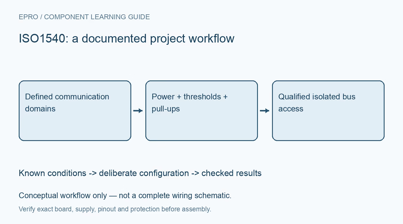
Plan ISO1540 communication with separate power domains, side-specific logic limits, pull-ups, clock stretching, bus timing and a clear isolation boundary. This is a documentation-based planning guide, not a report of independent hands-on testing.
1. Define the ISO1540 isolation boundary
ISO1540 transfers I2C-compatible communication across an isolation barrier. It does not supply isolated power or certify an entire board as safe for hazardous voltages. Draw the two communication and supply domains and identify every connection crossing between them. A programmer, oscilloscope ground or other cable can change the intended system boundary. Keep introductory functional evaluation within a protected low-voltage setup; do not improvise a high-voltage test to demonstrate a component isolation specification. Manufacturer documentation.
2. Distinguish ISO1540 from related devices
The shared documentation includes ISO1541, whose clock-channel direction differs from ISO1540. Confirm the actual component before assuming support for bidirectional clock behavior or target clock stretching. Review the controller and peripheral requirements for the intended bus. A matching data-channel connection does not establish that the clock path supports every transaction. Preserve the device identity, domain arrangement and communicating endpoints rather than describing the assembly only as a generic I2C isolation module. Manufacturer documentation.
3. Provide compatible power on both sides
Review each side’s supply limits, decoupling and startup arrangement using the exact board schematic. The signal barrier does not generate the required isolated supplies. Do not tie the domain returns together by habit when a real isolated boundary is intended; instead analyze the complete approved power and grounding arrangement. Also account for independently unpowered states. A functional low-voltage bus demonstration verifies communication under those conditions, not the insulation coordination or safety of a complete application. Manufacturer documentation.
4. Check side-specific low-level compatibility
The isolator uses documented input and output threshold arrangements that are not equivalent on both sides. Check the low-level voltage and sink-current requirements of the connected devices instead of assuming any ordinary GPIO or bus buffer is interchangeable. A nominally correct supply voltage is not enough. Preserve which endpoint is attached to which side. Some combinations can fail to recognize a valid low even while the idle high voltage appears entirely normal on a multimeter. Manufacturer documentation.
Newest in the store


5. Select pull-ups for each bus segment
Provide the documented pull-ups on the relevant segments and consider capacitance, sink capability and rise time for the complete connected network. Count resistors already present on breakout boards. Do not assume a resistor value copied from a short direct bus remains suitable after adding isolation, cabling and more peripherals. A successful address scan at one speed does not establish reliable data transfer across the intended load, timing and operating conditions. Manufacturer documentation.
6. Validate timing and clock stretching deliberately
Review propagation and bus-speed requirements alongside the actual controller implementation and peripheral behavior. Exercise the documented transactions and any expected clock stretching using compatible low-voltage equipment. Define bounded timeout and recovery handling without assuming that isolation resets a stuck peripheral automatically. Keep raw communication errors separate from valid measurement data. An isolator changes the electrical interface but does not remove address conflicts, application-protocol requirements or a sensor’s conversion-readiness constraints. Manufacturer documentation.
7. Keep communication evidence separate from safety claims
Retain component identity, supplies, domain wiring, endpoints, pull-ups, bus speed and observation conditions with evaluation results. Complete-system insulation, spacing, power and enclosure requirements require their own qualified design assessment. The linked TCA9546A guide concerns bus switching, not galvanic isolation or a substitute barrier. This ISO1540 workflow proposes documented communication checks and claims no independent insulation testing, universal device compatibility or hazardous-voltage certification based solely on a successful I2C read across an isolator. Manufacturer documentation.
Related reading: TCA9546A I2C Switch: 7 Checks for a Predictable Bus Tree.
Catalog note: The exact-part search did not return a matching Epro listing during preparation. Check the current catalog; this guide makes no price, availability or included-accessory claim.