


DRV5032 Hall Switch: 7 Checks for a Repeatable Magnet Event

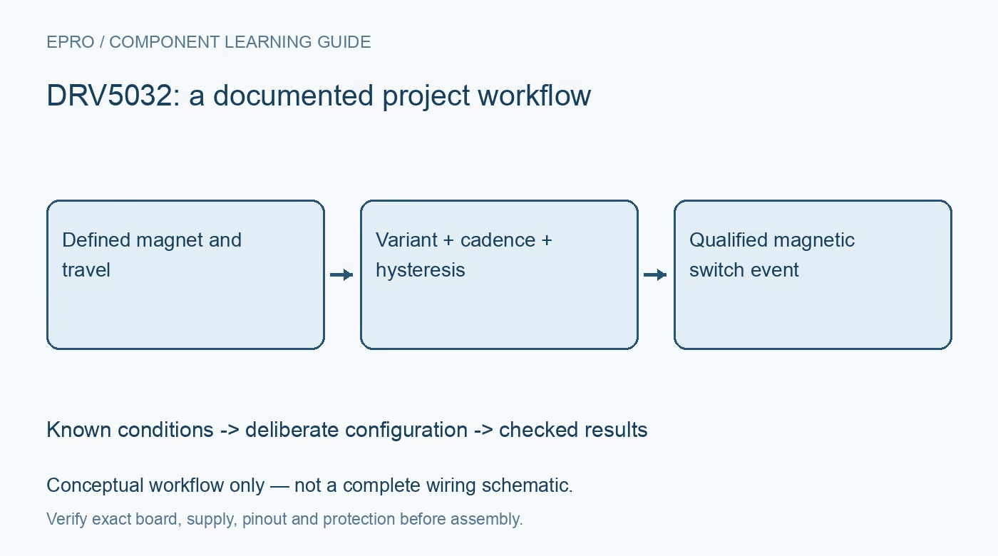
DRV5032 Hall Switch: 7 Checks for a Repeatable Magnet Event
Plan DRV5032 magnetic switching with the correct suffix, pole response, output type, sampling cadence, threshold hysteresis and installation geometry. This is a documentation-based planning guide, not a report of independent hands-on testing.
1. Define the DRV5032 switch objective
DRV5032 is a digital Hall-effect switch, not a three-axis magnetic-field meter or an angle encoder. Define the physical event the application needs to recognize, such as a cover position or a passing magnet. Record magnet identity, orientation, gap and travel. A binary output does not provide a universal distance estimate. The meaning of an asserted state depends on the actual magnetic geometry and on the device version installed in the assembly. Manufacturer documentation.
2. Identify the complete suffix and package
The family offers different magnetic thresholds, sampling rates, polarity responses and output arrangements. Confirm the full ordering option and carrier instead of selecting software or pull-ups from the base name alone. A replacement part can behave differently even if it fits the same footprint. Preserve identity with the application’s expected active state. This prevents an apparent mechanical fault from being diagnosed through code changes when the real cause is an unsuitable variant. Manufacturer documentation.
3. Match magnetic response to the assembly
Review whether the selected version responds to one polarity or both and how the magnet approaches the sensing axis. Assess manufacturing tolerances, nearby ferromagnetic material and mounting variation. A loose magnet moved by hand near a bare sensor does not establish the final switch boundary in an enclosure. Keep the intended travel and return path in the evaluation plan. A stronger magnet is not automatically a better solution if it changes the required release behavior. Manufacturer documentation.
4. Distinguish operate and release thresholds
The device’s documented operate and release points establish hysteresis. Evaluate approach and withdrawal conditions rather than reporting one convenient activation location. Threshold limits are not exact calibrated distances, and field strength depends on the magnet and geometry. Hysteresis supports stable switching near the boundary but does not remove every vibration or installation influence. Preserve the accepted mechanical region and its tolerance instead of claiming universal repeatability from a single static demonstration. Manufacturer documentation.
Newest in the store


5. Relate sampling cadence to target motion
The selected variant’s internal sampling rate determines when the magnetic condition is observed. A brief passing event can be missed even when a stationary magnet is detected reliably. Match motion speed and required latency to the documented behavior, and assess system timing as well as current consumption. Do not select the lowest-power option solely from its headline current. A host interrupt cannot recover a physical event that the switch never observed between its internal samples. Manufacturer documentation.
6. Use the correct electrical output interface
Review open-drain or push-pull behavior for the installed version and connect the host accordingly. Check supply, pull-up and input voltage limits rather than assuming every magnetic switch is an open collector. Define the application state through power-up, removal of supply and disconnected wiring. A GPIO edge is not automatically evidence of a real magnet event. Keep event qualification and startup handling deliberate so a routine reset does not unexpectedly activate a downstream function. Manufacturer documentation.
7. Retain the complete switching boundary
Record suffix, package, magnet, orientation, gap, travel, surrounding materials, cadence and output policy with observations. Reassess after enclosure or magnet changes. The related LDC0851 article describes conductive-target inductive switching, a different sensing principle rather than a compatible replacement. This DRV5032 workflow proposes traceable magnetic-event evaluation and claims no independent switching-distance accuracy, universal motion detection or safety certification merely because a compact low-power Hall sensor produces a digital output. Manufacturer documentation.
Related reading: LDC0851 Inductive Switch: 7 Checks for a Repeatable Threshold.
Catalog note: The exact-part search did not return a matching Epro listing during preparation. Check the current catalog; this guide makes no price, availability or included-accessory claim.