


TCA9546A I2C Switch: 7 Checks for a Predictable Bus Tree

TCA9546A I2C Switch: 7 Checks for a Predictable Bus Tree
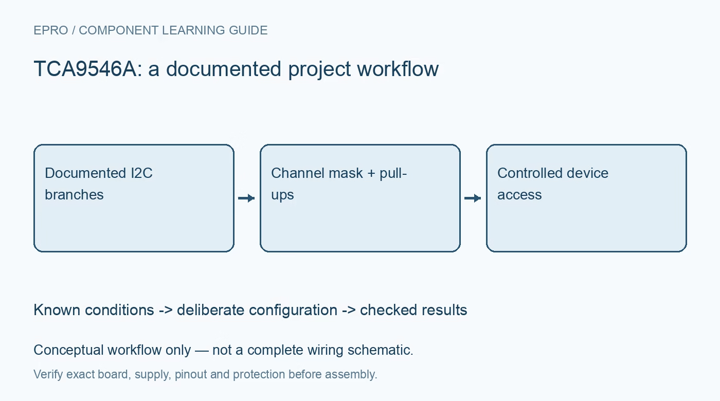
Plan a TCA9546A bus tree with four selectable branches, deliberate channel masks, compatible pull-ups and documented reset recovery. This is a documentation-based planning guide, not a report of independent hands-on testing.
1. Count the TCA9546A branches correctly
TCA9546A provides four downstream I2C switch channels. Do not copy an eight-channel assumption from a similarly named multiplexer or infer the branch count from a generic library example. Draw the upstream controller and each downstream branch with its attached devices and addresses. This topology record is the basis for deciding which channels may be enabled together and for understanding what a successful address scan actually reveals about the connected hardware. Manufacturer documentation.
2. Distinguish a switch from an address translator
Selecting a branch changes which downstream bus is connected; it does not rewrite a peripheral address. Devices with the same address can be accessed separately when their conflicting branches remain appropriately isolated. Enabling both conflicting branches defeats that separation. Also check whether a downstream device conflicts with the switch address itself. A device discovery routine should report the selected branch with each result instead of treating all matching addresses as one unique physical sensor. Manufacturer documentation.
3. Treat channel selection as a bit mask
The control register allows channels to be selected in combinations, not only as a single numbered route. Construct the intended mask explicitly and reject unsupported bits. For an introductory setup with identical-address peripherals, begin with all channels off and enable only the required branch. Preserve the selected mask in diagnostics. An accidental cumulative mask can reconnect an earlier branch and produce communication behavior that looks intermittent even though the software is consistently selecting the wrong topology. Manufacturer documentation.
4. Design pull-ups for the connected segments
Review pull-ups, bus voltage domains and the switch supply requirements using the manufacturer guidance. Check the effective network when more than one branch is connected, including pull-ups already fitted on carrier boards. Do not assume that any low-voltage switch automatically makes arbitrary voltage combinations safe. The relevant signal levels and current loading belong to the complete connected path. A topology that works with one short cable may not behave the same after adding several populated branches. Manufacturer documentation.
Newest in the store


5. Separate address discovery from functional checks
After selecting a branch, confirm the expected device identity or a documented safe read rather than stopping at an acknowledgment. Record unexpected addresses and make configuration errors visible. A scan does not verify sensor calibration, conversion readiness or correct data interpretation. Keep device-specific drivers separate from the branch-selection layer so the software can deliberately select a route before each access, particularly when different tasks share the same upstream controller. Manufacturer documentation.
6. Plan reset and stuck-bus recovery
The active-low reset function and documented power-up behavior are useful parts of recovery planning. Review how deselecting channels can isolate a downstream fault, while recognizing that a selected peripheral or an upstream electrical problem may still require additional handling. Do not assume that retrying the same transaction indefinitely restores a stuck bus. Define a bounded recovery sequence and preserve the failed branch identity. Resetting the switch is not the same as resetting every attached peripheral. Manufacturer documentation.
7. Keep the topology with every test result
Retain the switch address, branch mask, downstream addresses, pull-up arrangement, supply conditions and recovery observations. Recheck the arrangement after changing cables or attaching another breakout with built-in resistors. The related TCA9548A scan guide provides a comparison workflow for a different channel count, not matching masks or guaranteed carrier wiring. This TCA9546A guide proposes controlled bus access without claiming that any arbitrary bus length, voltage combination or collection of same-address devices has been independently validated. Manufacturer documentation.
Related reading: TCA9548A I2C Multiplexer: Arduino Channel Scan in 7 Steps.
Catalog note: The exact-part search did not return a matching Epro listing during preparation. Check the current catalog; this guide makes no price, availability or included-accessory claim.