


TMP112 Temperature Sensor: 7 Checks for the Right Data Format

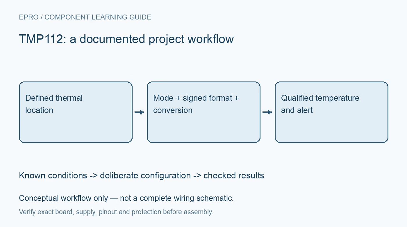
TMP112 Temperature Sensor: 7 Checks for the Right Data Format
Plan a TMP112 temperature readout around the exact variant, normal or extended format, conversion timing and alert behavior before trusting a displayed value. This is a documentation-based planning guide, not a report of independent hands-on testing.
1. Identify the exact variant and package
Start with the complete ordering code, not just a board label saying TMP112. The family documentation covers variants and packages with different supply, accuracy and pin-function details. Compare the schematic against the pin table for the actual device and check whether the board exposes the signal your firmware expects. A pinout or alert assumption copied from a different package can turn a reasonable software plan into the wrong electrical connection. Manufacturer documentation.
2. Check the supply and bus at the device
Measure the intended supply at the sensor and identify the rail used by the I2C pull-ups. A microcontroller accepting a particular voltage does not establish that every device on the bus can tolerate it. Include the address-pin configuration, decoupling and shared-ground arrangement in the build record. Evaluate bus rise time with the complete wiring and modules attached rather than assuming that successful address detection proves reliable temperature transactions. Manufacturer documentation.
3. Match decoding to normal or extended mode
The temperature register is not a generic signed sixteen-bit temperature value. Normal mode uses a twelve-bit result; extended mode uses a thirteen-bit format with different alignment within the returned word. Read the configuration and select the corresponding decoding path before sign extension and scaling. The nominal temperature increment is 0.0625 degrees Celsius. Test the decoder with documented positive and negative examples, including a value crossing zero, rather than validating only room-temperature output. Manufacturer documentation.
4. Separate register access from a completed conversion
A readable register is not evidence that a new conversion has finished. After reset, the temperature register initially represents zero until the first conversion completes. Define the startup wait and the freshness rule for continuous or one-shot operation using the selected configuration. Mark data invalid during initialization and after a failed transaction. Otherwise a cleanly formatted zero, or a repeatedly read older result, can look more credible than it deserves. Manufacturer documentation.
Newest in the store


5. Treat placement as part of the measurement
The device reports its own local temperature, which is influenced by board copper, nearby regulators, airflow and the enclosure. Decide whether the project needs board temperature, enclosure air or another thermal location before choosing where to mount it. Allow the complete assembly to settle before comparing against a reference. A software offset derived beside a warm processor may not remain useful after a layout, power-state or enclosure change. Manufacturer documentation.
6. Validate the complete alert policy
Where the selected device and package provide the needed alert connection, document comparator or interrupt behavior, polarity, thresholds, hysteresis and fault-queue settings. Then check assertion and release separately. A temperature returning below a limit does not necessarily produce the same clearing behavior in every configured mode. Keep startup behavior and host acknowledgement in the test plan. Treat the alert as an input to a defined response, not as an independent thermal safety system. Manufacturer documentation.
7. Save a reproducible readout record
Record the ordering code, board revision, supply, address, configuration word, raw temperature bytes and decoded units together. Include startup, negative-value decoding, disconnected-bus handling and an intentionally stale sample in software checks. Compare stable readings at several relevant conditions without claiming that one comparison establishes the full accuracy specification. Preserve any limits of the reference instrument and thermal arrangement. The useful result is a traceable temperature record, not merely a plausible number on a display. Manufacturer documentation.
Related reading: TMP114 Temperature Sensor: 7 Checks for Low-Voltage Thermal Data.
Catalog note: The exact-part search did not return a matching Epro listing during preparation. Check the current catalog; this guide makes no price, availability or included-accessory claim.