


LMP91000 Electrochemical AFE: 7 Checks Before Reporting Gas Levels

LMP91000 Electrochemical AFE: 7 Checks Before Reporting Gas Levels
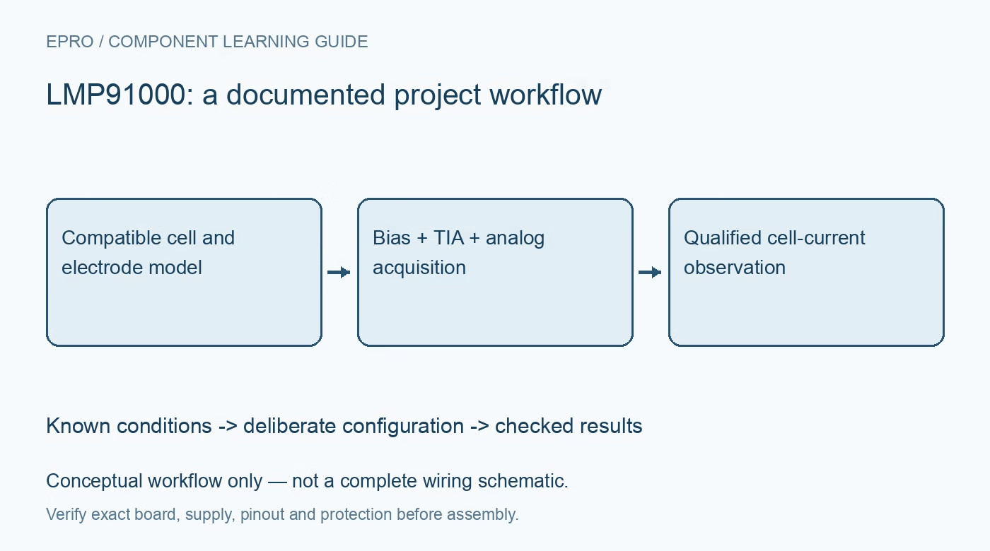
Plan LMP91000 sensing with a compatible electrochemical cell, correct electrode bias, TIA and reference settings, analog acquisition and justified calibration. This is a documentation-based planning guide, not a report of independent hands-on testing.
1. Define the LMP91000 sensor responsibility
LMP91000 is a configurable analog front end for appropriate electrochemical sensors. It is not a gas-sensitive element, a complete detector or a digital register that directly reports parts per million. Begin with the exact sensor manufacturer’s electrode, bias, sensitivity and operating requirements. Record whether the cell uses the supported two- or three-electrode arrangement. An AFE that communicates successfully does not establish that the connected cell detects the intended substance or that a finished instrument is safe to rely on. Manufacturer documentation.
2. Connect electrodes according to the cell model
Distinguish working, reference and counter electrode responsibilities using the documented application arrangement. Do not interchange connections based on cable color or assume every electrochemical sensor uses the same polarity. Review supply and input limits with the actual carrier. Keep evaluation within suitable protected low-voltage conditions. Incorrect electrode bias can change the observation or affect a sensor; selecting an apparently plausible amplifier gain cannot compensate for a fundamentally unsuitable cell connection or operating condition. Manufacturer documentation.
3. Set bias and internal zero deliberately
The bias setting uses the supported fraction and polarity relative to the selected reference arrangement. Internal zero establishes another responsibility in the analog transfer path. Preserve both settings rather than calling every midpoint voltage the sensor bias. Check reference quality, allowable range and sensor requirements before applying power. A successful register readback shows the configured bits, not that the physical electrode potentials and cell behavior satisfy the intended measurement model under the actual installed conditions. Manufacturer documentation.
4. Choose TIA gain for signal and headroom
The transimpedance stage converts cell current into an output-voltage change. Select gain, load arrangement and any supported external components from the expected current range, bandwidth and available output swing. As a numerical illustration, a 10-microamp current magnitude through 35 kilohms corresponds to a 350-millivolt change from the configured zero, with direction determined by the actual circuit. This is arithmetic, not a measured calibration. Include tolerance, offset, noise and clipping in the complete acquisition assessment. Manufacturer documentation.
Newest in the store


5. Treat I2C control and analog readout separately
Use the documented interface and module-enable arrangement to configure the AFE. The measurement output remains analog and needs a compatible ADC, reference and sampling policy. Do not mistake acknowledged register traffic for a completed current conversion. Preserve mode identity when the supported temperature-related function changes the meaning of VOUT. A voltage acquired under one operating mode cannot be interpreted with another mode’s transfer relationship merely because the same ADC channel and connector were used. Manufacturer documentation.
6. Establish calibration without hazardous improvisation
Gas concentration requires a justified sensor-specific relationship, including baseline, sensitivity, temperature, cross-sensitivity, aging and relevant environmental conditions. Raw cell current is not universally proportional to one gas under every circumstance. Follow qualified calibration procedures and suitable approved reference equipment; do not generate or release hazardous gases as an improvised demonstration. An unqualified hobby assembly must not substitute for a certified personal safety or environmental alarm. Preserve the reference conditions and uncertainty with any concentration claim. Manufacturer documentation.
7. Keep model and evidence with every result
Retain cell identity, electrode arrangement, reference, bias, zero, TIA, mode, ADC configuration and calibration conditions with observations. Reject saturated or unavailable data explicitly. The linked ADC guide can support planning the downstream voltage acquisition but does not validate a chemical-sensor model. This LMP91000 workflow proposes documentation-based interface checks and reports no independent gas calibration, selective detection performance or safety certification of a finished instrument from the presence of a programmable electrochemical front end alone. Manufacturer documentation.
Related reading: ADS1018 SPI ADC: 7 Checks Before Scaling a Conversion.
Catalog note: The exact-part search did not return a matching Epro listing during preparation. Check the current catalog; this guide makes no price, availability or included-accessory claim.