


BQ25895 Charger: 7 Checks for the Real Input-Current Limit

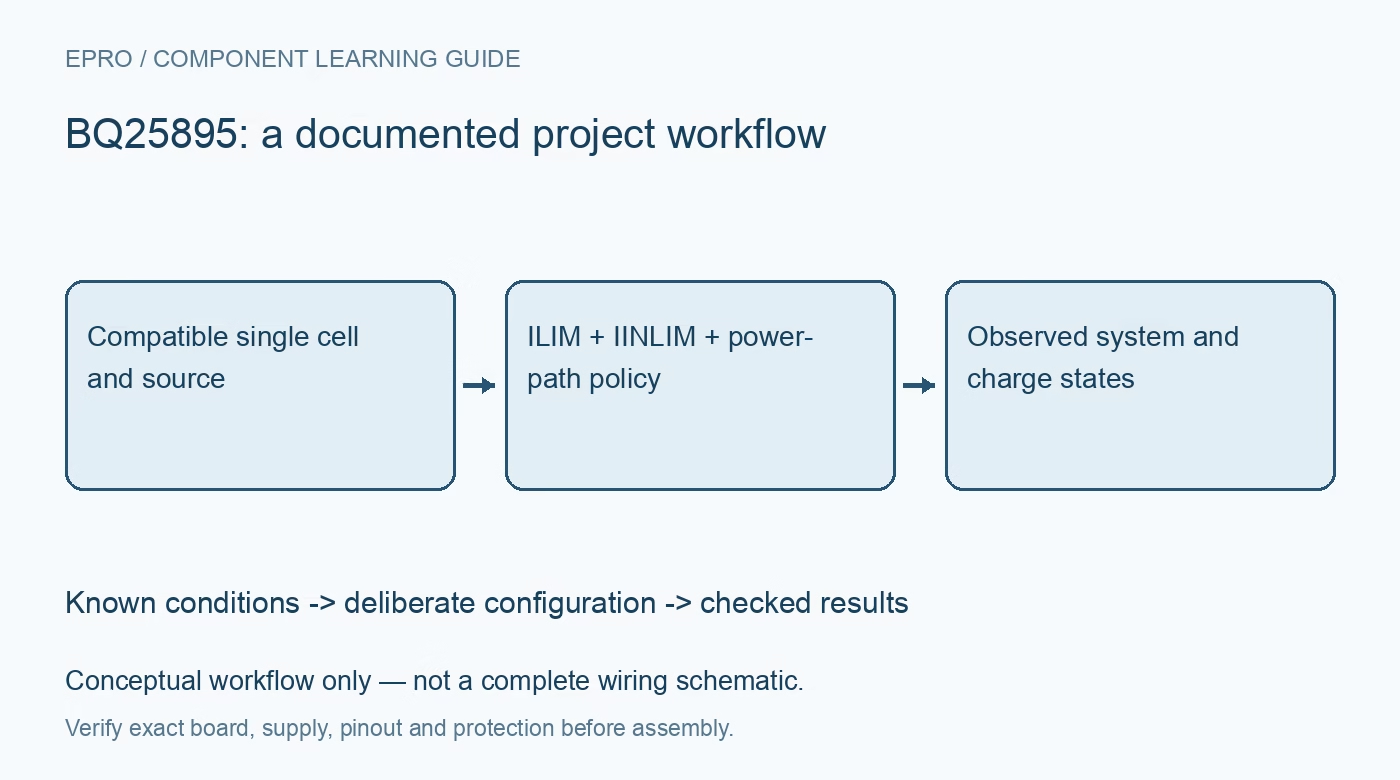
BQ25895 Charger: 7 Checks for the Real Input-Current Limit
Review a BQ25895 single-cell charger around source capability, ILIM and IINLIM limits, NVDC power paths and thermal behavior before relying on a charge setting. This is a documentation-based planning guide, not a report of independent hands-on testing.
1. Confirm the cell chemistry and charging topology
The BQ25895 is intended for a compatible single lithium-ion or lithium-polymer cell system. Its charging stage is a buck converter, with a separate boost operating function; it is not a general multicell buck-boost charger. Match the cell manufacturer’s voltage, current and temperature requirements to the complete circuit. Use a known protected cell arrangement and appropriate test equipment. Do not infer safe charging settings from a board’s printed current rating or a battery’s physical size. Manufacturer documentation.
2. Draw the source, system and battery paths
Identify VBUS, SYS, BAT and PMID on the actual schematic before attaching loads or measurement equipment. The NVDC power-path arrangement distributes available input power between the running system and battery charging. A programmed charge current is therefore not a guarantee that the cell receives that current while the system is active. Include connector resistance, cable drop and source capability in the budget. Record where each current measurement is taken so input, system and battery currents are not confused. Manufacturer documentation.
3. Apply both input-current limiting mechanisms
When EN_ILIM enables the pin function, the ILIM hardware clamp remains part of the input-current limit alongside the register-controlled policy. Input-current optimization can further adjust the effective limit; it does not remove an enabled ILIM clamp. Inspect EN_ILIM, the fitted resistor, IINLIM and the applicable optimization result instead of assuming one register write establishes the source budget. Read back settings and compare against a controlled source and load. Lower-than-expected current can be correct limiting behavior rather than a failed charger. Manufacturer documentation.
4. Separate source detection from power negotiation
The documented input-source detection and D-plus/D-minus behavior do not provide universal USB-C Power Delivery negotiation. Determine what the actual connector, cable and upstream source permit, and add the required role or negotiation circuitry where applicable. Do not raise voltage or current merely because a supply advertises a larger maximum rating. Likewise, input-current optimization and dynamic power management are not unrestricted solar MPPT. Evaluate the intended source type and operating policy explicitly rather than borrowing a feature name from another charger. Manufacturer documentation.
Newest in the store


5. Preserve temperature and protection policies
Check the TS network and the configured charging temperature behavior against the cell and board requirements. Preserve protective functions rather than bypassing them to make charging begin during an unexplained fault. Evaluate heat in the charger, inductor, connectors and cell under representative system load. High charge and boost-current headlines depend on electrical and thermal conditions; they are not continuous promises for every module. Stop a controlled test when limits or unexpected heating are encountered. Manufacturer documentation.
6. Plan watchdog and mode transitions
Review which settings return to defaults after a watchdog event, reset or source transition. Re-establish the approved input and charging limits before accepting normal operation, and log why reconfiguration occurred. Boost operation introduces a different power-flow role that must be coordinated with the connected source and load. Test that role change deliberately using the documented control sequence. Do not assume that a previously successful charge configuration also describes safe behavior when the system begins supplying external power. Manufacturer documentation.
7. Validate states rather than inventing battery percentage
Use the available ADC and status information to support diagnostics, while recognizing that this charger is not by itself a precision state-of-charge gauge. Compare source, system and battery behavior through startup, active load, charge progression and source removal. Retain settings, measurements and temperature conditions together. Define a safe response to communication loss or conflicting status. The resulting guide should establish a traceable charging policy for a compatible single-cell assembly, not infer battery health or capacity from one voltage reading. Manufacturer documentation.
Related reading: BQ25798 Charger: 7 Checks for Cell Count and Source Policy.
Catalog note: The exact-part search did not return a matching Epro listing during preparation. Check the current catalog; this guide makes no price, availability or included-accessory claim.