


TMCS1123 Hall Current Sensor: 7 Checks for the Right Variant

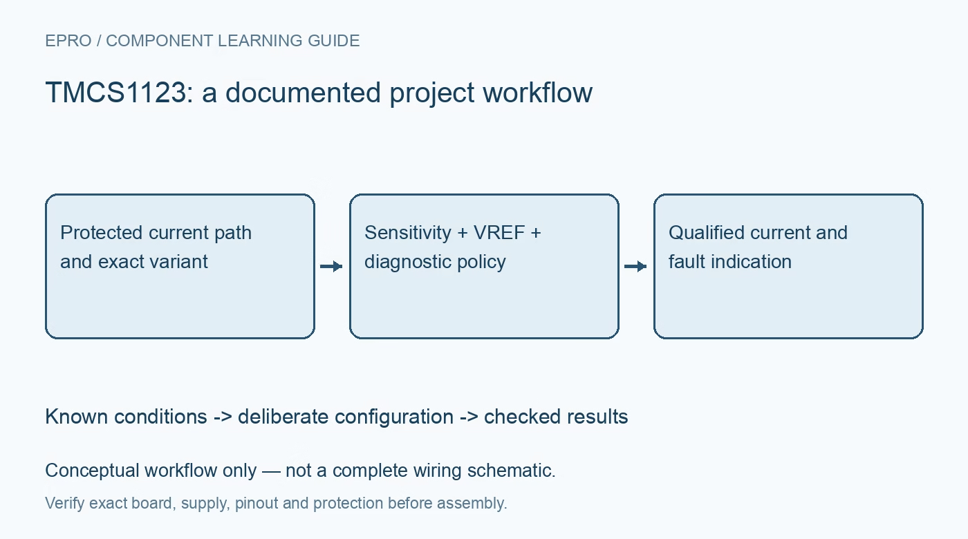
TMCS1123 Hall Current Sensor: 7 Checks for the Right Variant
Select a TMCS1123 variant by sensitivity and zero-current reference, then check analog range, current-path heating and diagnostic behavior before using its output. This is a documentation-based planning guide, not a report of independent hands-on testing.
1. Decode the complete device suffix
The TMCS1123 family includes different sensitivities and zero-current output voltages. Select the exact ordering option before calculating current or importing a library constant. The linear current span also depends on the output supply and available analog swing; it need not be symmetric around zero for every option. Save the fitted marking and comparison-table entry with the design. A conversion based on a neighboring suffix can be consistently wrong while still looking smooth and repeatable. Manufacturer documentation.
2. Define the physical current path and direction
Current passes through the package conductor and produces the magnetic field sensed internally. Identify IN+ and IN– orientation, current sign and the connections used by the complete assembly. Begin with a protected, current-limited low-voltage circuit and secure wiring. The headline measurable current range is not an unconditional continuous-current rating for every board. Check the device safe-operating-area information together with conductor heating, PCB copper, connector capability, ambient temperature and the duration of anticipated current pulses. Manufacturer documentation.
3. Use the correct zero-current reference model
The device provides a zero-current reference output and a fixed sensitivity for the selected option. Do not automatically assume a supply-ratiometric output or that every device sits at half the supply at zero current. Compare the actual VOUT and VREF behavior with the selected variant’s transfer relationship. Check whether the ADC can accept both the zero point and expected excursion. Preserve the raw voltages and reference conditions during initial characterization rather than storing only an already-converted current value. Manufacturer documentation.
4. Treat ADC scaling as a separate measurement stage
The host ADC reference, resolution, input range and acquisition behavior contribute their own errors and limits. An isolated Hall measurement does not protect an ADC from an incompatible analog output voltage on its local side. Check offset, sensitivity tolerance, noise and bandwidth together, then choose filtering and sampling for the intended signal. State whether the result is instantaneous current, an average or a separately computed RMS estimate. Those quantities require different processing and should not share an ambiguous label. Manufacturer documentation.
Newest in the store


5. Do not turn component isolation into a board claim
The package provides galvanic isolation with documented insulation specifications, but the complete assembly must preserve appropriate spacing, materials and construction. Working-voltage, transient and insulation-test ratings describe different conditions and are not interchangeable. Do not present a component withstand figure as certification of a breakout board or finished instrument. For development, remain with protected low-voltage conditions. Any higher-energy deployment needs a qualified system-level design and review beyond a sensor bring-up checklist. Manufacturer documentation.
6. Review diagnostics and overcurrent timing by option
The family includes diagnostic and overcurrent functions whose wiring and behavior require the exact datasheet. In particular, the D71 option adds an overcurrent masking interval, so short events and sustained events do not produce the same response. Do not apply that timing to every suffix. Check output type, pull-up requirements, startup validity and the host’s reaction to an asserted indication. A diagnostic signal should feed a defined response policy rather than being treated as proof of automatic system protection. Manufacturer documentation.
7. Qualify the final geometry and operating conditions
Compare known bounded currents in the assembled board at relevant directions, temperatures and signal rates. Include zero current, near-limit output swing and a safely simulated fault indication where practical. Ambient-field rejection reduces interference but does not remove the need to review nearby conductors, magnets and mechanical placement. Retain variant, supply, reference and ADC settings with the results. Separate demonstrated repeatability from the manufacturer’s specified limits, and do not describe documentation review as independent hands-on validation. Manufacturer documentation.
Related reading: TMCS1100 Hall Current Sensor: 7 Checks for a Bounded Reading.
Catalog note: The exact-part search did not return a matching Epro listing during preparation. Check the current catalog; this guide makes no price, availability or included-accessory claim.