


DAC5571 8-Bit DAC: 7 Checks for Correct Codes and Output

DAC5571 8-Bit DAC: 7 Checks for Correct Codes and Output
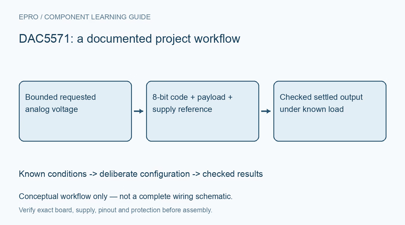
Build a DAC5571 output plan around its eight-bit data packing, supply-based reference, power-down controls and real load limits before trusting a requested voltage. This is a documentation-based planning guide, not a report of independent hands-on testing.
1. Confirm the eight-bit device and board
The DAC5571 is an eight-bit single-channel I2C DAC. Related devices in the same family use other resolutions, so confirm the complete part number before reusing a driver. Inspect the board supply, address connection and output path against the schematic. A compatible connector does not prove a compatible data format. Record whether any buffer, filter or protection component lies between the DAC pin and the point the application calls its analog output. Manufacturer documentation.
2. Treat the supply as part of the reference
The output range is based on VDD, rather than an independently selected precision reference input. Supply tolerance and noise therefore matter to the requested output voltage. Check local decoupling and measure the actual supply during representative operation. Do not use a nominal five-volt software constant without considering the real rail. Include the DAC’s own errors and output-headroom limitations separately; a correct digital code does not establish that the resulting voltage equals an ideal supply-scaled calculation. Manufacturer documentation.
3. Map requested voltage into a bounded code
Define an explicit policy for requests below zero, above the available range or between representable levels. The eight-bit code space contains 256 possible values, ending at code 255; the ideal top-code result is not automatically the full supply voltage. Clamp or reject out-of-range requests deliberately and state the chosen rounding method. Keep units clear at the API boundary so a millivolt request cannot be mistaken for a raw code. Validate boundary cases before attaching a sensitive load. Manufacturer documentation.
4. Pack data into the documented payload positions
The two payload bytes contain control information as well as the eight meaningful DAC data bits. Follow the documented bit positions rather than sending a raw sixteen-bit number or copying a twelve-bit-family packing routine unchanged. Test the exact bytes for zero, midscale and the highest code, including power-down control bits. Capture an I2C transaction when possible and compare it with the intended frame. A slave acknowledgement does not establish that the desired output code occupied the correct field. Manufacturer documentation.
Newest in the store


5. Separate update speed from analog settling
The supported bus modes and digital update capability do not guarantee that an arbitrary output step settles within one transaction time. Evaluate the documented analog settling behavior with the real load and any external filtering. Include the chosen I2C timing and pull-up arrangement, especially before using faster modes. If the output drives a sampled ADC or a control loop, define when the new voltage is considered usable. A rapid series of writes can otherwise produce a waveform unlike the intended static setpoints. Manufacturer documentation.
6. Specify startup and power-down output behavior
The power-on reset establishes a zero output until a valid write, but the application still needs to assess supply ramps and connected circuitry. The power-down modes change the output connection and are not equivalent to leaving an actively buffered zero-volt setpoint. Select the required behavior from the mode table and test recovery timing. Document host-reset behavior separately from DAC power loss. An application restart should not assume that every analog component has returned to its own power-on state. Manufacturer documentation.
7. Check output voltage before and after loading
Start with safe unloaded measurements at several codes, then repeat with the intended bounded load. Verify both sourcing and sinking conditions relevant to the circuit without treating short-circuit figures as recommended operating current. Record supply, code, payload, settling interval and measurement point together. Include a failed transaction and recovery test in the software plan. The result should establish a useful output range for that assembly rather than promise rail-to-rail precision or power-drive capability in every application. Manufacturer documentation.
Related reading: DAC60501 DAC: 7 Checks for a Predictable Voltage Output.
Catalog note: The exact-part search did not return a matching Epro listing during preparation. Check the current catalog; this guide makes no price, availability or included-accessory claim.