


TPS3890 Supervisor: 7 Checks for Sense and Reset Timing

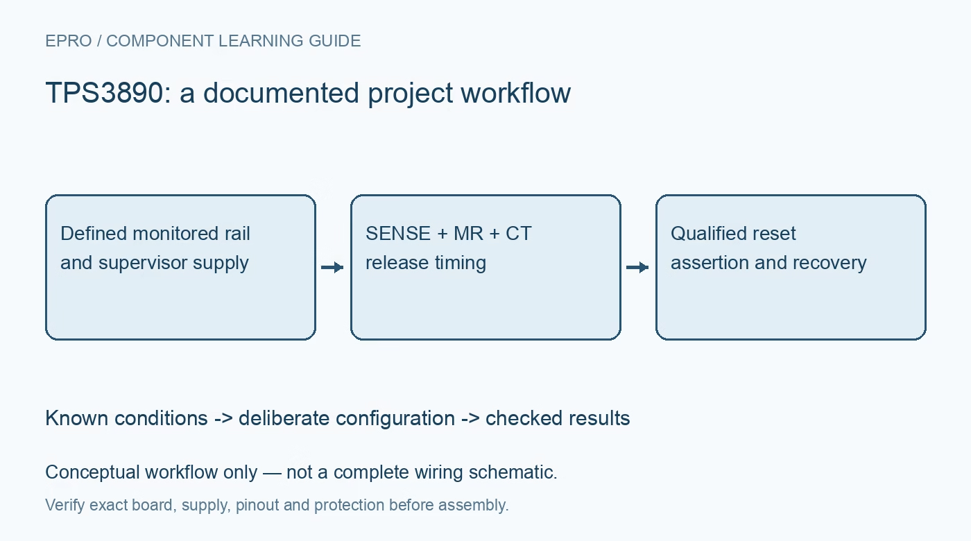
TPS3890 Supervisor: 7 Checks for Sense and Reset Timing
Plan a TPS3890 reset policy around the separate SENSE input, exact threshold option, open-drain output, manual reset and timing capacitor before enabling a host. This is a documentation-based planning guide, not a report of independent hands-on testing.
1. Separate the monitored rail from device power
The TPS3890 has a SENSE input distinct from VDD. Draw which rail powers the supervisor and which rail it monitors before interpreting its reset output. The monitored rail may disappear while the supervisor remains powered, or the reverse may occur. Both cases require review. Check SENSE limits and supervisor supply validity for the actual sequence rather than assuming that a separate input permits every voltage combination during startup, shutdown or partial power loss. Manufacturer documentation.
2. Choose the exact threshold option
The family includes fixed and adjustable threshold choices. Identify the complete ordering code and compare the applicable threshold tolerance with the host’s minimum operating voltage and supply tolerance. Where a divider is used, include resistor tolerance, input leakage and the effect of the surrounding circuit. Do not infer the threshold from an example schematic alone. A rail being nominally above a chosen threshold is not enough if expected droop or tolerance can place the host outside its valid operating region. Manufacturer documentation.
3. Design the open-drain reset connection
RESET requires an appropriate pull-up and does not actively drive a high level like a push-pull output. Choose the pull-up rail and resistance using the reset input requirements, sink capability and power-state behavior of every connected device. If several sources share the net, verify their output types and release conditions. Include debugger and external-connector paths in the review. A valid supervisor decision can still become an invalid host logic level through an unsuitable pull-up or back-power path. Manufacturer documentation.
4. Calculate release delay with the real capacitor
The CT capacitor programs reset-release timing over the documented range; it is not a promise of an exact delay independent of component tolerance and leakage. Use the manufacturer timing relationship and specified limits, then evaluate the selected capacitor under operating conditions. Include PCB contamination, parasitic capacitance and loading where relevant. Keep the timing node away from inappropriate probing or external circuitry. Check both the shortest acceptable delay and the longest tolerable recovery interval for the host. Manufacturer documentation.
Newest in the store


5. Include manual reset in the release policy
MR can force reset independently of the monitored voltage. Define its normal logic level, allowed drive source and behavior when left externally disconnected. When MR returns inactive, release still depends on the monitored voltage and the delay logic. Test manual assertion while the rail is healthy and while it is recovering from undervoltage. Do not treat the input as a mechanical-button interface without reviewing signal quality, pulse requirements and any application-specific need for debouncing or filtering. Manufacturer documentation.
6. Exercise rail dips and incomplete recovery
Capture reset assertion and release with controlled supply ramps and brief disturbances. Check what happens if SENSE or MR becomes invalid again before the release interval completes. Compare the results with the documented timing behavior rather than a simplified fixed-delay software model. Also test loss of the supervisor’s own supply. A reset circuit cannot guarantee meaningful powered logic behavior below its specified validity conditions, and a host remaining energized through another interface may require additional design attention. Manufacturer documentation.
7. Verify host recovery instead of only the reset edge
Observe the host and its external peripherals through undervoltage, manual reset and restoration of both power domains. Confirm that outputs remain appropriate during reset and that communication devices are reinitialized on release. Keep the rail waveform, CT selection, pull-up network and host outcome in one record. This device supports a supply-reset policy; it is not automatically a watchdog or a comprehensive safety controller. The completed qualification should establish reliable recovery for the actual assembly and its intended operating envelope. Manufacturer documentation.
Related reading: TPS3839 Supervisor: 7 Checks for a Fixed Reset Policy.
Catalog note: The exact-part search did not return a matching Epro listing during preparation. Check the current catalog; this guide makes no price, availability or included-accessory claim.