


ADS8681 SAR ADC: 7 Checks for Bipolar Range and Code Mapping

ADS8681 SAR ADC: 7 Checks for Bipolar Range and Code Mapping
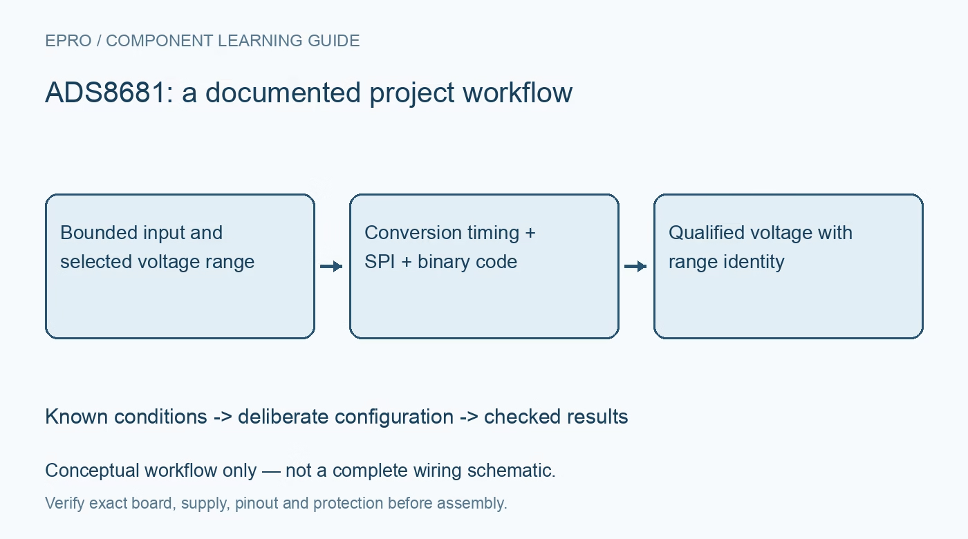
Plan ADS8681 acquisition around its selected bipolar or unipolar range, straight-binary result, pseudo-differential input and SPI timing before scaling a sample. This is a documentation-based planning guide, not a report of independent hands-on testing.
1. Identify the converter and its separate supplies
The ADS8681 belongs to a family with different maximum conversion rates. Confirm the fitted part rather than applying the ADS8685 or ADS8689 timing limits indiscriminately. The analog and digital interface supplies also have different roles and allowed ranges. Review the actual board schematic, reference arrangement and host logic domain before connecting signals. A single-supply analog front end does not mean that every exposed pin accepts the same voltage or that the entire module is already level translated. Manufacturer documentation.
2. Establish the programmed range before conversion
The input range is selected through device registers, with both bipolar and unipolar options available. Read back the intended selection during initialization and retain that range identifier with every accepted sample. A valid raw word can represent a different voltage after a configuration change. Check reference selection and settling as part of the same operation. Do not infer the active range from the sensor’s expected amplitude, a library default or the label printed beside an input connector. Manufacturer documentation.
3. Respect the pseudo-differential input boundary
The input measures AIN_P relative to AIN_GND under documented restrictions. It is not a general floating differential interface that permits an arbitrary voltage on both terminals. Review signal return, common ground and the permitted AIN_GND region before attaching a source. Input overvoltage protection is a survival-related feature, not an extension of the linear measurement range. Begin with protected, current-limited low-voltage signals and check the entire external protection and filtering arrangement against the intended range. Manufacturer documentation.
4. Decode bipolar results as straight binary
The output uses straight-binary coding for both bipolar and unipolar ranges. In a bipolar range, zero volts is near midscale rather than represented by a signed zero word. Reusing a two’s-complement decoder from another ADC can therefore produce completely wrong values. Calculate voltage from the selected negative full-scale boundary, full-scale span and sixteen-bit code. Validate the mapping with documented endpoint and midpoint examples, including values just above and below zero, before relying on live measurements. Manufacturer documentation.
Newest in the store


5. Match conversion and serial-transfer timing
Review the selected multiSPI mode, conversion-start behavior, serial clock requirements and returned-data sequence together. A working register read does not establish correct timing at the desired sample rate. Use the manufacturer timing diagrams to determine which conversion the received result represents and when it is valid. Capture a representative transaction during bring-up if suitable equipment is available. Keep the host acquisition schedule separate from the analog source settling and reference requirements rather than treating a fast SPI transfer as a complete measurement cycle. Manufacturer documentation.
6. Distinguish active alarms from retained events
The device provides input and supply-related alarm information with active and tripped behaviors. Their clearing rules are not interchangeable: the retained event information can be affected by reading the alarm register. Define which software task owns those reads and how it records a fault before clearing evidence. Include the configured alarm output and thresholds in the test plan. An alarm-free sample is not proof of calibration, and a retained alarm does not necessarily describe the present input condition. Manufacturer documentation.
7. Save raw codes with measurement context
Qualify bounded known voltages across the chosen range using the final front-end wiring. Record raw data, range, reference, sample timing and alarm status together. Exercise a reset, a deliberate range change and a communication interruption so stale data cannot silently acquire a new scale. Compare noise and accuracy at the intended throughput instead of equating sixteen output bits with sixteen bits of absolute accuracy. The useful result is a traceable voltage observation, not merely a plausible number after a generic scaling formula. Manufacturer documentation.
Related reading: ADS1262 Precision ADC: 7 Checks Before Trusting 32-Bit Data.
Catalog note: The exact-part search did not return a matching Epro listing during preparation. Check the current catalog; this guide makes no price, availability or included-accessory claim.