


LM3880 Rail Sequencer: 7 Checks Beyond Flag Release Order

LM3880 Rail Sequencer: 7 Checks Beyond Flag Release Order
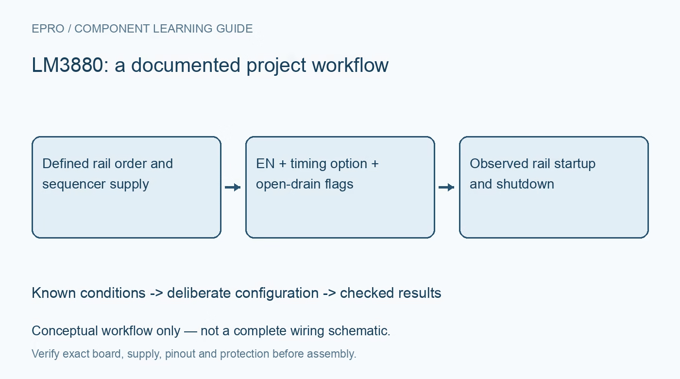
Plan LM3880 power sequencing around the exact timing option, open-drain flag limits and real regulator startup and shutdown behavior before approving rail order. This is a documentation-based planning guide, not a report of independent hands-on testing.
1. Identify the complete timing and sequence option
The LM3880 uses configured timing and sequence options associated with the orderable device. Confirm the exact suffix and its manufacturer timing tables before designing around a particular interval. The datasheet’s reference to EPROM customization does not mean the finished part exposes a host I2C programming interface. Do not assume every LM3880 uses the same delays or release order. Save the fitted ordering code beside the required rail sequence so procurement substitutions receive an explicit engineering review. Manufacturer documentation.
2. Separate enabling a rail from observing it
The three flags control sequencing, but they do not provide three independent measurements confirming that the controlled rails reached their target voltages. A flag release tells the regulator to proceed through its own enable and startup behavior. Draw the actual rail ramp and power-good requirements separately. If the system needs feedback-qualified sequencing, determine what additional monitoring or a different architecture must supply. Timed control alone cannot detect every regulator that starts slowly, current limits or fails to rise. Manufacturer documentation.
3. Check the sequencer supply and enable threshold
Review the sequencer supply range, local bypassing and the conditions establishing EN. The precision enable threshold can support a defined triggering arrangement, but that arrangement still needs resistor, capacitor and leakage analysis where used. Check slow supply ramps and a source interruption rather than assuming a clean digital edge always starts the sequence. The sequencer must remain in a valid operating condition long enough to provide the required behavior; its own disappearing supply can undermine an otherwise sensible shutdown plan. Manufacturer documentation.
4. Respect open-drain flag pull-up limits
The flag outputs require pull-ups and do not actively drive high. Check the allowed pull-up voltage relative to the sequencer supply, including the documented limit involving VDD plus 0.3 volts. Do not treat each flag as an arbitrary high-voltage-tolerant enable translator. Review regulator enable thresholds, pull-up resistance and any alternate power source on the net. Include partially powered states: an enabled regulator or external programmer may energize an interface while the sequencer supply is absent or still ramping. Manufacturer documentation.
Newest in the store


5. Budget actual startup timing between rails
Combine flag timing with regulator enable delay, soft start, output capacitance and load-dependent ramp behavior. The gap between two flag releases is not necessarily the gap between two rails becoming usable. Capture both control flags and physical rail voltages under representative source and load conditions. Compare that evidence with the processor or FPGA’s sequencing requirements. A timing option that looks correct using nominal regulator values may leave insufficient margin when a later rail rises quickly and an earlier one starts slowly. Manufacturer documentation.
6. Validate physical shutdown order independently
The normal sequence can release flags in one order and assert them in the corresponding configured power-down order, but the actual rails also depend on stored energy, active discharge and remaining loads. One rail may stay above its relevant threshold long after its regulator is disabled. Test the intended EN-driven shutdown while the sequencer remains powered appropriately. Include a rapid restart and incomplete discharge. Correct flag order is useful evidence, but it does not establish the complete electrical power-down sequence by itself. Manufacturer documentation.
7. Save a system-level sequencing record
Record ordering code, supply, enable waveform, flag pull-ups, regulator settings and observed rail crossings together. Exercise representative startup, controlled shutdown, brownout and interrupted restart conditions with sensitive loads protected. Define how the host remains reset until its actual power requirements are satisfied rather than assuming the last flag proves every rail is healthy. The completed result should establish an acceptable sequence for the assembled system, with clear limits on timing assumptions and no claim that this simple sequencer replaces every required supervisor. Manufacturer documentation.
Related reading: TPS2121 Power Mux: 7 Checks for Deliberate Source Selection.
Catalog note: The exact-part search did not return a matching Epro listing during preparation. Check the current catalog; this guide makes no price, availability or included-accessory claim.