


TCA9543A I2C Switch: 7 Checks for Channel Interrupt Routing

TCA9543A I2C Switch: 7 Checks for Channel Interrupt Routing
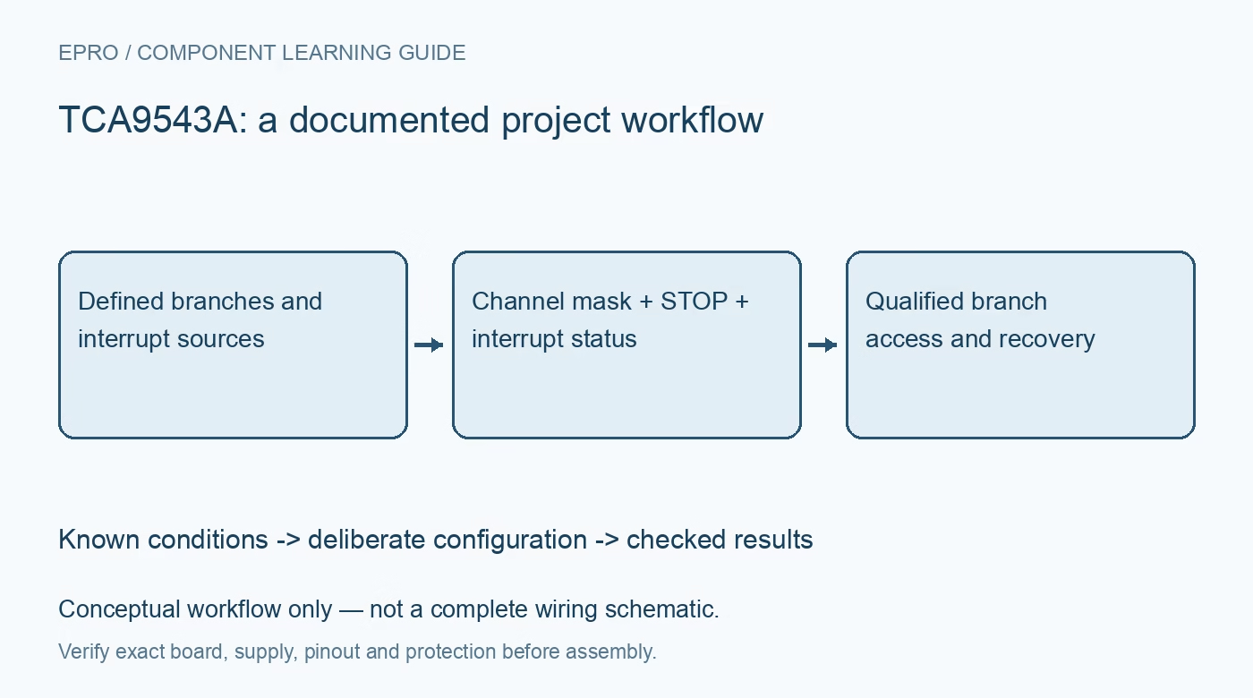
Use the TCA9543A with a deliberate channel mask, STOP-controlled switching and downstream interrupt clearing before routing same-address devices on separate branches. This is a documentation-based planning guide, not a report of independent hands-on testing.
1. Map the two branches and interrupt lines
The TCA9543A provides two bidirectional I2C switch channels plus interrupt handling. Draw the upstream bus, each downstream bus and each active-low interrupt input separately. Include device addresses and existing pull-ups on every segment. Unlike a generic channel multiplexer example, this design also needs a host policy for discovering which branch requested service. The switch does not automatically forward a device-specific interrupt message; it provides electrical indication and status that the host must interpret. Manufacturer documentation.
2. Choose channel masks deliberately
Either channel or both channels can be selected through the control register. This flexibility does not make simultaneous selection safe when the two branches contain devices with the same address. For duplicate-address parts, select only the intended branch before accessing the shared address. Save the desired mask in the driver and verify control-register reads as appropriate. Power-on and reset deselect both channels, so host recovery must restore the intended path rather than assuming that the previous branch remains connected. Manufacturer documentation.
3. Complete selection with the required STOP
A channel becomes active after the documented STOP condition following the control-register transaction. Do not replace that boundary with an immediate repeated-start access and assume the new branch is already connected. Keep switch selection and downstream transfer as clearly separated driver operations. Test the transaction sequence at the actual bus rate, especially when a generic I2C helper tries to combine operations. An acknowledged control byte is not by itself proof that the next transfer reached the newly selected endpoint. Manufacturer documentation.
4. Design pull-ups for the connected topology
The pass-switch arrangement needs suitable pull-ups and voltage relationships; it is not the same architecture as an active current-source buffer. Review the manufacturer voltage-translation conditions and limits for the chosen upstream and downstream rails. When both branches are enabled, their capacitance and pull-up networks interact with the upstream segment. Evaluate rise time and low-state sink current for that connected network. Successful communication with one short branch does not establish timing margin after another loaded branch is added. Manufacturer documentation.
Newest in the store


5. Interpret interrupts even on deselected branches
An interrupt input can be detected while its associated data channel is deselected. The shared open-drain output alerts the host, and the control-register status identifies the branch input state. This lets software choose a branch before interrogating its devices, but it does not identify which of several devices on that branch asserted the line. Define the servicing order and check every relevant source. Reading the switch status is a routing step, not an automatic acknowledgement of the downstream event. Manufacturer documentation.
6. Clear the actual source and handle shared assertions
After selecting the indicated branch, follow the endpoint’s own procedure to read and clear its interrupt condition. Then confirm whether other sources or the other branch remain asserted. Include the host interrupt input’s trigger mode, pull-up and recheck policy in the design. If an interrupt input is unused, connect it according to the manufacturer guidance instead of leaving it floating. Avoid an interrupt-service routine that repeatedly selects a branch but never removes the underlying low level. Manufacturer documentation.
7. Use RESET as a bounded recovery mechanism
The active-low RESET input resets the switch state machine and disconnects both channels, which can help isolate a downstream bus held low. It does not repair the endpoint that caused the fault. Test recovery with a safely simulated stuck branch, restore the intended channel mask and verify correct endpoint data afterward. Record rail states, reset timing and interrupt status together. The completed qualification should demonstrate predictable routing and servicing, not promise that a switch eliminates every bus fault or address conflict automatically. Manufacturer documentation.
Related reading: TCA9546A I2C Switch: 7 Checks for a Predictable Bus Tree.
Catalog note: The exact-part search did not return a matching Epro listing during preparation. Check the current catalog; this guide makes no price, availability or included-accessory claim.