


BQ25628 Charger: 7 Checks for Ship Mode and Reliable Wake-Up

BQ25628 Charger: 7 Checks for Ship Mode and Reliable Wake-Up
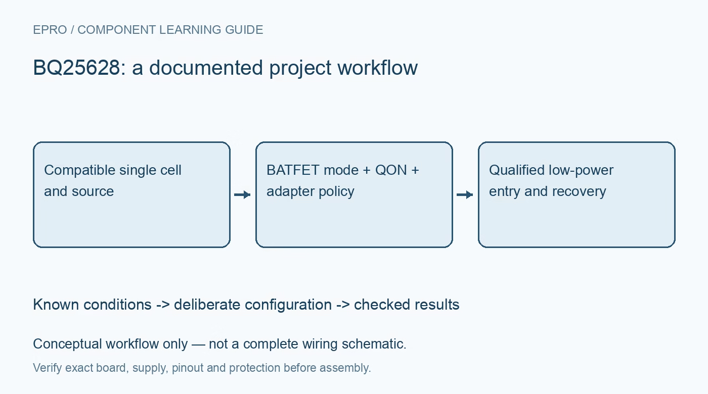
Review BQ25628 battery-only, ship and shutdown behavior with QON, adapter detection and reset defaults before promising a low-power product can wake itself. This is a documentation-based planning guide, not a report of independent hands-on testing.
1. Confirm the charger and its family-specific pins
The BQ25628 is a single-cell buck charger with NVDC power-path management. Its ILIM and TS_BIAS functions differ from the input-source-detection arrangement of BQ25629. Do not import the latter’s D-plus/D-minus assumptions into a BQ25628 schematic. Identify the exact device and connector implementation before defining source policy. Use a compatible protected lithium-ion or lithium-polymer cell arrangement, and preserve the cell manufacturer’s charging limits rather than choosing settings from a module’s headline current alone. Manufacturer documentation.
2. Draw which loads remain battery connected
Identify the system node, battery node, accessory path and any circuitry connected directly to the cell. Opening the internal BATFET does not disconnect loads that bypass it on the PCB. Include dividers, protection circuitry, regulators and external interfaces in the battery-leakage budget. The charger’s very low mode-current figures are component specifications, not a guarantee of finished-product shelf life. Measure the complete product in the intended mode instead of multiplying a datasheet typical value into an unsupported storage-duration claim. Manufacturer documentation.
3. Treat ship mode and shutdown as different states
Ship mode and shutdown both turn off the battery-to-system path and disable I2C, but their wake-up policies differ. The distinction is essential if the host loses power when it requests the transition. Define the intended state explicitly and confirm the BATFET control encoding from the register map. A software command labelled sleep should not obscure which charger state was actually requested. Keep converter high-impedance mode and a system power reset separate from these low-leakage states. Manufacturer documentation.
4. Match the wake source to the selected state
Ship mode can be exited through the documented QON low interval or by an adapter connection. Shutdown instead requires an adapter connection; QON has no effect in that state. A product that promises button-only recovery must therefore not silently enter shutdown. Check that the physical button, its wiring and the required pulse duration remain usable without the main processor. Do not rely on a future I2C write to recover a mode that has already disabled the bus interface. Manufacturer documentation.
Newest in the store


5. Check adapter presence when requesting entry
Mode-entry behavior depends on whether an adapter is present and on the applicable BATFET configuration. A request made while VBUS is valid may be ignored or produce a different documented path state rather than the assumed battery-only ship transition. Verify the status and actual system-power outcome instead of treating a successful register transaction as proof of entry. Include the configured delay, source removal and active accessory modes in the sequence review, with loads held in a safe condition. Manufacturer documentation.
6. Re-establish approved settings after wake-up
Exit from ship mode or shutdown resets registers to their power-on defaults. The host must restore and verify the approved charging, source-current and operating policies before assuming the previous configuration still applies. For BQ25628, review the ILIM hardware clamp and its enable control alongside the register current limit. Preserve temperature safeguards and check watchdog behavior separately. A successful processor reboot does not establish that the charger resumed the exact limits used before low-power entry. Manufacturer documentation.
7. Qualify recovery on the complete assembly
Begin with a protected current-limited source and a compatible cell, then test battery-only operation, each selected low-power entry, QON timing and adapter-triggered recovery. Log charger status, system voltage, battery current and restored configuration together. Include a failed or interrupted host transaction before entry. Confirm that the product cannot become stranded in a state its intended user cannot exit. The handover should establish measured entry and recovery behavior, not confuse internal ADC diagnostics with a precision battery state-of-charge estimate. Manufacturer documentation.
Related reading: BQ25895 Charger: 7 Checks for the Real Input-Current Limit.
Catalog note: The exact-part search did not return a matching Epro listing during preparation. Check the current catalog; this guide makes no price, availability or included-accessory claim.