


OPT3005 Ambient Light Sensor: 7 Checks Around Active Infrared

OPT3005 Ambient Light Sensor: 7 Checks Around Active Infrared
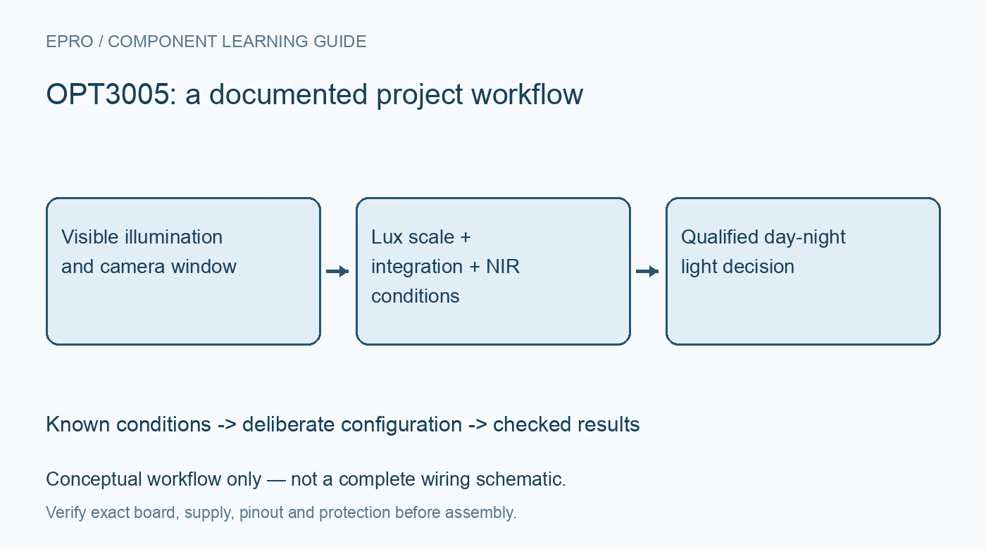
Plan OPT3005 visible-light decisions around its 0.02-lux scale, conversion timing and camera optics, especially when 850-nm or 940-nm illumination is active. This is a documentation-based planning guide, not a report of independent hands-on testing.
1. Define visible-light sensing separately from infrared
The OPT3005 is intended to measure illuminance as perceived by the human eye while strongly rejecting near-infrared light. That makes it relevant to cameras with active infrared illumination, but it does not turn the device into an infrared power meter. State whether the application needs a day-night decision, display adjustment or another visible-light threshold. Record which infrared emitters operate nearby and which optical surfaces can reflect their light into the sensor’s viewing region. Manufacturer documentation.
2. Check device supply and interface limits independently
The sensor supply range and its I/O tolerance are separate specifications. Do not infer that a five-volt-tolerant interface permits a five-volt device supply. Inspect the module’s regulator, pull-up rail and address connections against the actual schematic. Include startup and partially powered conditions when another camera domain remains active. A successful I2C address scan is only a communication check; it does not establish the optical operating mode, configured range or freshness of the data being returned. Manufacturer documentation.
3. Use this device’s exponent-and-mantissa scale
The result combines an exponent and a twelve-bit mantissa. The documented conversion is lux = 0.02 × 2^E × R, using the exponent E and mantissa R fields. Do not copy a 0.01-lux scale from a different sensor simply because the register arrangement looks familiar. Test the decoder using several documented ranges and retain raw result words during development. Automatic ranging extends dynamic range; it does not produce a directly linear twenty-three-bit lux register. Manufacturer documentation.
4. Allow the complete conversion interval
Choose the integration setting using the response speed and noise requirements of the application. The documented conversion interval includes overhead beyond the nominal integration time, so a fixed one-hundred-millisecond host loop is not automatically a fresh-reading policy for the shorter setting. Initialize the desired operating mode and use the documented conversion-ready behavior. Mark startup and failed transactions invalid. Reading a register repeatedly during one integration does not provide multiple independent observations of the changing light level. Manufacturer documentation.
Newest in the store


5. Qualify the real window with infrared on and off
Strong near-infrared rejection does not remove the need to test the assembled optical path. Compare representative visible light with the camera’s infrared illumination both enabled and disabled. Include window tint, incidence angle, internal reflections and emitter placement in the conditions. A bare-sensor result cannot establish performance behind an arbitrary cover glass. Keep visible-light reference measurements separate from infrared-emitter electrical power; they describe different quantities and should not be used as interchangeable calibration targets. Manufacturer documentation.
6. Add a stable day-night decision policy
Define thresholds, hysteresis, minimum dwell time and handling of unavailable readings before connecting the measurement to an illuminator or camera mode. If changing camera mode also changes the light reaching the sensor, the control action can feed back into the next measurement. Test that loop explicitly. Where an interrupt is used, review its configured assertion and clearing behavior. A raw lux crossing alone does not establish a robust day-night policy under reflections, headlights or other short optical disturbances. Manufacturer documentation.
7. Save conditions with every threshold evaluation
Log decoded lux, raw word, integration setting, conversion validity, infrared state and the resulting camera decision. Exercise gradual dusk-like changes, abrupt visible illumination and a blocked or contaminated window under controlled conditions. Include a bus failure so the application has a deliberate fallback rather than acting on an old value. Distinguish repeatable switching from absolute photometric accuracy. The completed qualification should apply to the assembled camera and its defined optical environment, not promise perfect rejection under every possible source or enclosure geometry. Manufacturer documentation.
Related reading: OPT3004 Light Sensor: 7 Checks for a Valid Lux Reading.
Catalog note: The exact-part search did not return a matching Epro listing during preparation. Check the current catalog; this guide makes no price, availability or included-accessory claim.