


TPS22965 Load Switch: 7 Checks for Bias, Inrush and Discharge

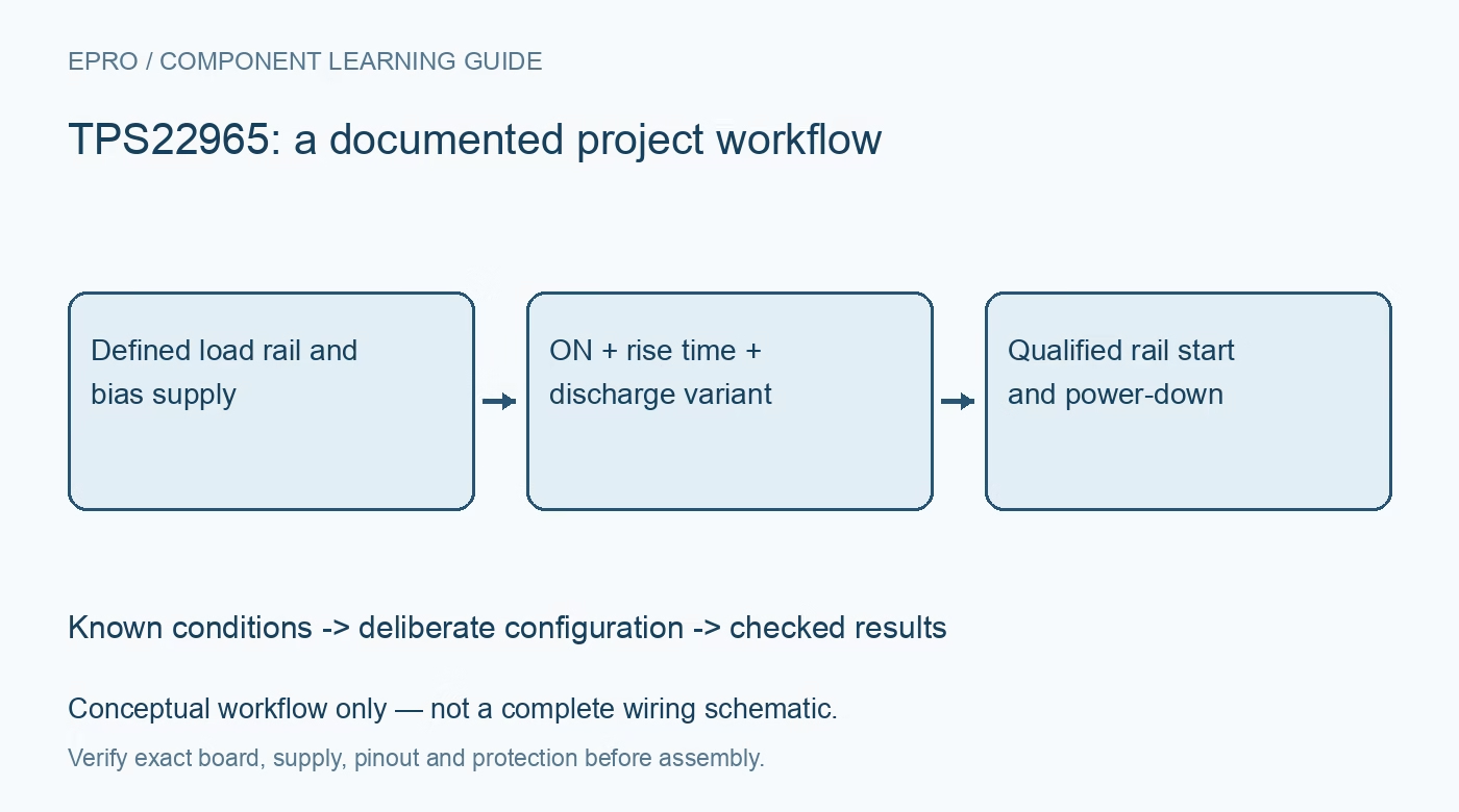
TPS22965 Load Switch: 7 Checks for Bias, Inrush and Discharge
Review a TPS22965 switched rail around VIN versus VBIAS, rise-time control, actual load current and the discharge difference between TPS22965 and TPS22965N. This is a documentation-based planning guide, not a report of independent hands-on testing.
1. Distinguish the discharge variants
TPS22965 and TPS22965N share a load-switch function but differ when disabled. TPS22965 includes quick output discharge, while the N variant does not. Confirm the fitted suffix before predicting whether the output is actively pulled toward ground or left disconnected. Record the exact device beside the required shutdown behavior. A board substituted for lower leakage or availability can otherwise change how long a downstream circuit remains energized after firmware commands the rail off. Manufacturer documentation.
2. Check VIN and VBIAS as separate requirements
The switch can pass a low-voltage rail, but its bias supply has its own minimum and maximum limits. The recommended VIN range is also bounded by VBIAS. Do not connect both pins to a low sensor rail merely because that rail is inside the headline input-voltage range. Draw their actual sources and startup order. Check the ON signal against the applicable logic thresholds while both supplies move through startup, normal operation and shutdown. Manufacturer documentation.
3. Choose rise time from the actual capacitance
The CT setting controls the output ramp. Use the manufacturer relationship and relevant conditions to estimate rise time, then evaluate the attached capacitance and load. Capacitive inrush depends on how quickly the rail rises and how much charge is required. A nominal capacitor value on the schematic may differ from effective capacitance under bias. Also include downstream devices that begin drawing current partway through the ramp; they can change the load well before the final voltage is reached. Manufacturer documentation.
4. Do not confuse slew control with a current limiter
A slower rise can reduce capacitive inrush, but that does not turn the device into a programmable overcurrent regulator or an electronic fuse. Protect the source and load using an appropriate system arrangement. Evaluate switch dissipation, copper area, connections and temperature at the intended continuous current. The maximum current rating and low typical resistance are not unconditional promises for every breakout layout. Establish thermal margin rather than treating the onset of protection elsewhere in the system as a normal operating point. Manufacturer documentation.
Newest in the store


5. Analyze quick discharge with the full output network
On TPS22965, disabling the switch connects an internal discharge resistor between output and ground. Its typical resistance describes a discharge path, not an instantaneous collapse or a regulated output-zero source. Output capacitance and remaining load determine the decay. Check whether another source, interface pin or programmer can feed the switched rail while discharge is active. Review those alternate paths before assuming that the output is isolated from every other powered domain. Manufacturer documentation.
6. Include partially powered downstream interfaces
A sensor rail being off does not ensure the sensor is unpowered if communication or interrupt pins remain driven. Review back-power paths, host reset states and the documentation for each downstream device. Define when the host may communicate relative to the measured rail ramp and device startup delay. Keep switch turn-on timing separate from sensor readiness. A rail crossing its nominal voltage does not prove that a peripheral has completed initialization or that it can safely drive the bus. Manufacturer documentation.
7. Validate startup and shutdown under representative loads
Capture VIN, VBIAS, ON, output voltage and source current through startup, shutdown and a rapid restart. Repeat with representative capacitance and load within the approved limits. Check both the intended discharge behavior and any unexpected retained voltage. Save the fitted suffix, CT selection and measurement conditions together. The finished result should establish an orderly rail-control policy for the actual assembly, without claiming current limiting, reverse isolation or instantaneous power removal merely from the phrase load switch. Manufacturer documentation.
Related reading: TPS22918 Load Switch: 7 Checks for an Orderly Sensor Rail.
Catalog note: The exact-part search did not return a matching Epro listing during preparation. Check the current catalog; this guide makes no price, availability or included-accessory claim.