


DRV8210 Motor Driver: 7 Checks for Package and Stop-State Timing

DRV8210 Motor Driver: 7 Checks for Package and Stop-State Timing
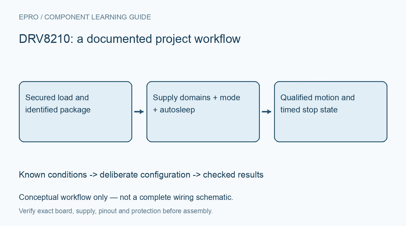
Plan DRV8210 control around the actual package, VM and VCC domains, selected interface and timed autosleep before assuming that a disabled motor remains braked. This is a documentation-based planning guide, not a report of independent hands-on testing.
1. Identify the package before choosing an interface
The DRV8210 family documentation covers package-dependent connections and features. The small DRL version supports the PWM interface, while the DSG implementation provides additional control choices and separate supply arrangements. Confirm the full ordering code and schematic before selecting a software driver. Do not assume that every board exposes MODE or an independent logic supply. A familiar family name is not enough to establish which truth table and startup behavior apply to the assembled motor stage. Manufacturer documentation.
2. Separate motor power from logic power where provided
In the DSG arrangement, VM and VCC serve different functions and have different allowed ranges. A stable logic supply can support operation while the motor supply is low, but that does not permit arbitrary voltage on the logic pins. Compare each pin and supply with the recommended conditions for the actual package. Record where motor current returns and how the host ground is connected. Begin with a protected current-limited source and a mechanically secured load. Manufacturer documentation.
3. Make the mode-selection condition explicit
The available DSG control interfaces include PWM, PH/EN and independent half-bridge operation. MODE selection changes the meaning of the input states, so establish the documented selection condition before interpreting a command. Include the pin state during power-up and host reset rather than reviewing only the final firmware configuration. A floating mode pin can be a deliberate interface selection, not merely an unconnected input. Preserve that choice on the schematic and in the driver’s configuration record. Manufacturer documentation.
4. Distinguish an initial brake from the later sleep state
In PH/EN mode, taking EN low initially applies the documented brake behavior. If the inactive condition persists beyond the autosleep interval, the bridge becomes high impedance. Therefore a long disabled interval is not necessarily a permanently braked motor. Check the timing against the application’s mechanical requirements and verify the wake-up sequence before resuming motion. A software variable called enable cannot by itself establish whether the physical outputs are presently braking, coasting or asleep. Manufacturer documentation.
Newest in the store


5. Review half-bridge operation as a different topology
Independent half-bridge operation can control separate loads or support the documented parallel arrangement, but its input and default-output behavior differ from ordinary full-bridge control. Draw the load connections and current paths for the selected topology before wiring outputs together. Do not treat a higher headline parallel peak-current figure as a continuous rating for an arbitrary board. Check switching states, thermal conditions and returned inductive energy using the specific manufacturer guidance rather than a generic two-input motor example. Manufacturer documentation.
6. Keep protection separate from motion feedback
Undervoltage, overcurrent and thermal protection support device fault handling; they do not establish shaft position or a calibrated stall detector. Review retry and recovery behavior before deciding what the host should do after a fault. If the application needs load or position information, provide and qualify the required sensing separately. Include the power source’s response to braking and reversal. A protected driver can still be part of a mechanically unsafe system if the commanded or fault-induced state is not controlled. Manufacturer documentation.
7. Qualify the complete time-dependent sequence
Test startup, drive, a short stop, an extended stop, sleep recovery and host reset with a bounded mechanical load. Record package, mode, supply voltages, input states and observed motion together. Check timing as well as static levels so an initially correct brake state is not assumed to persist indefinitely. Progress to representative loads only within the electrical and thermal envelope. The final record should explain what the motor does over time, not merely show that it once rotated in both directions. Manufacturer documentation.
Related reading: DRV8213 Motor Driver: 7 Checks Before Trusting Stall Detection.
Catalog note: The exact-part search did not return a matching Epro listing during preparation. Check the current catalog; this guide makes no price, availability or included-accessory claim.