


BQ25120A Wearable PMIC: 7 Checks for Rails and Watchdog Defaults

BQ25120A Wearable PMIC: 7 Checks for Rails and Watchdog Defaults
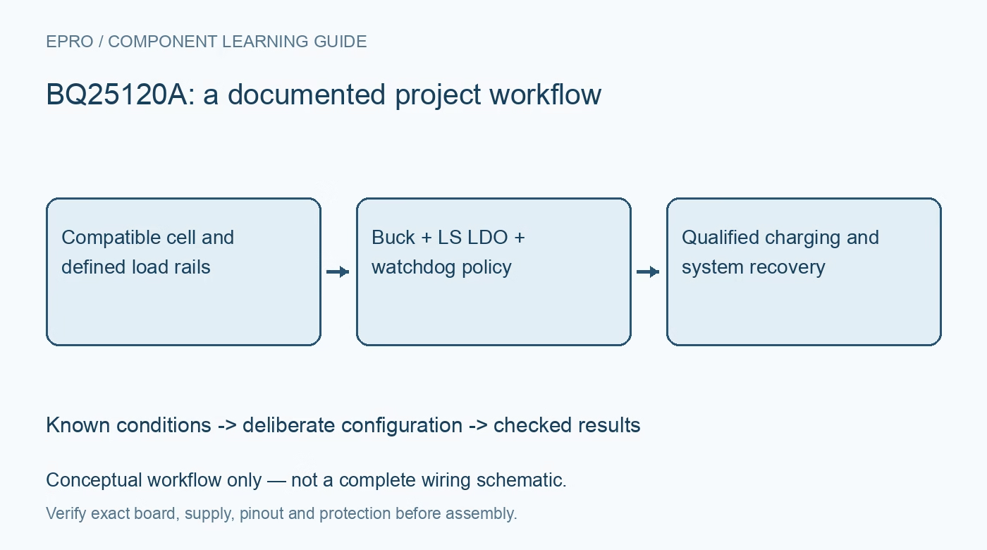
Plan a BQ25120A wearable power system around its linear charger, default buck rail, LS/LDO mode, host watchdog and verified ship-mode recovery sequence. This is a documentation-based planning guide, not a report of independent hands-on testing.
1. Separate the charger from its regulated outputs
The BQ25120A integrates a linear battery charger, a buck regulator and a configurable load-switch or LDO function. Those blocks have different current paths and constraints. Draw the input, battery, system and auxiliary-output connections before assigning current budgets. A system-output capability is not the same as allowable charging current. Use a compatible protected cell arrangement and preserve its manufacturer-specified voltage, current and temperature requirements rather than treating a wearable-oriented PMIC as safe for every small lithium battery. Manufacturer documentation.
2. Check the buck rail before connecting the processor
The buck output has a documented default setting, including a nominal 1.8-volt startup configuration. Confirm that the fitted processor, sensors and communication pull-ups tolerate the actual startup rail before firmware can change it. Read back the selected voltage after configuration and review reset behavior. A processor that requires a different rail cannot depend on code that only runs after that rail has already been established. Treat the boot-power dependency as a hardware requirement, not merely an initialization detail. Manufacturer documentation.
3. Distinguish load-switch mode from regulated LDO mode
The auxiliary output is configurable and defaults to load-switch behavior rather than automatically providing the programmed LDO voltage. Inspect the mode, enable control and supply path before attaching a voltage-sensitive load. A readable LDO setting does not prove that regulation is active. Document how LSCTRL and the register settings interact in the intended operating state. Check off-state loading and alternate power paths so disabling the output does not leave the connected circuit unexpectedly powered through another interface. Manufacturer documentation.
4. Budget source power, charging and system load together
The input-current limit, charge-current setting and active loads interact with the device’s operating loops. Include the linear charger’s voltage drop and resulting heat in the power budget. A programmed charge current is not a guarantee that the battery receives that current while the system is active or thermally constrained. Retain the temperature-sense and safety functions. Compare status with measured input, battery and load behavior before interpreting reduced charging as a configuration failure. Manufacturer documentation.
Newest in the store


5. Treat the host watchdog as a configuration boundary
After I2C activity starts the watchdog, continued host transactions service the documented timer. If it expires, most registers return to defaults, with the specific exceptions listed in the datasheet. That can change more than a status flag: it can affect the rail and charging policy the application assumed was persistent. Define how the host services the watchdog and restores verified settings after recovery. Test a stalled host rather than assuming that one successful startup write is permanent. Manufacturer documentation.
6. Define ship entry and button recovery deliberately
Ship mode disconnects internal paths under documented entry conditions and can be exited through the applicable input-supply or MR-button sequence. Review the required button timing and release behavior, not just an intuitive short press. Entry also depends on whether a valid input supply is present. Check the actual wiring and the physical controls available when the processor is no longer powered. A product should not promise a user-accessible wake function that depends on firmware running inside the powered-down domain. Manufacturer documentation.
7. Qualify the product through resets and power changes
Record startup rails, auxiliary-output mode, charge settings and relevant status during source insertion, source removal, watchdog expiration and ship-mode recovery. Include a host reset and a failed transaction while keeping the cell and loads within safe limits. Measure the complete product’s low-power current instead of extending one typical component figure into an unsupported battery-life claim. The voltage-based battery monitor also should not be described as a precision state-of-charge gauge without the additional modelling and validation such an estimate requires. Manufacturer documentation.
Related reading: BQ25185 Charger: 7 Checks for a Compatible Power Path.
Catalog note: The exact-part search did not return a matching Epro listing during preparation. Check the current catalog; this guide makes no price, availability or included-accessory claim.