


TMP390 Temperature Switch: 7 Checks for Resistor Codes and Trips

TMP390 Temperature Switch: 7 Checks for Resistor Codes and Trips
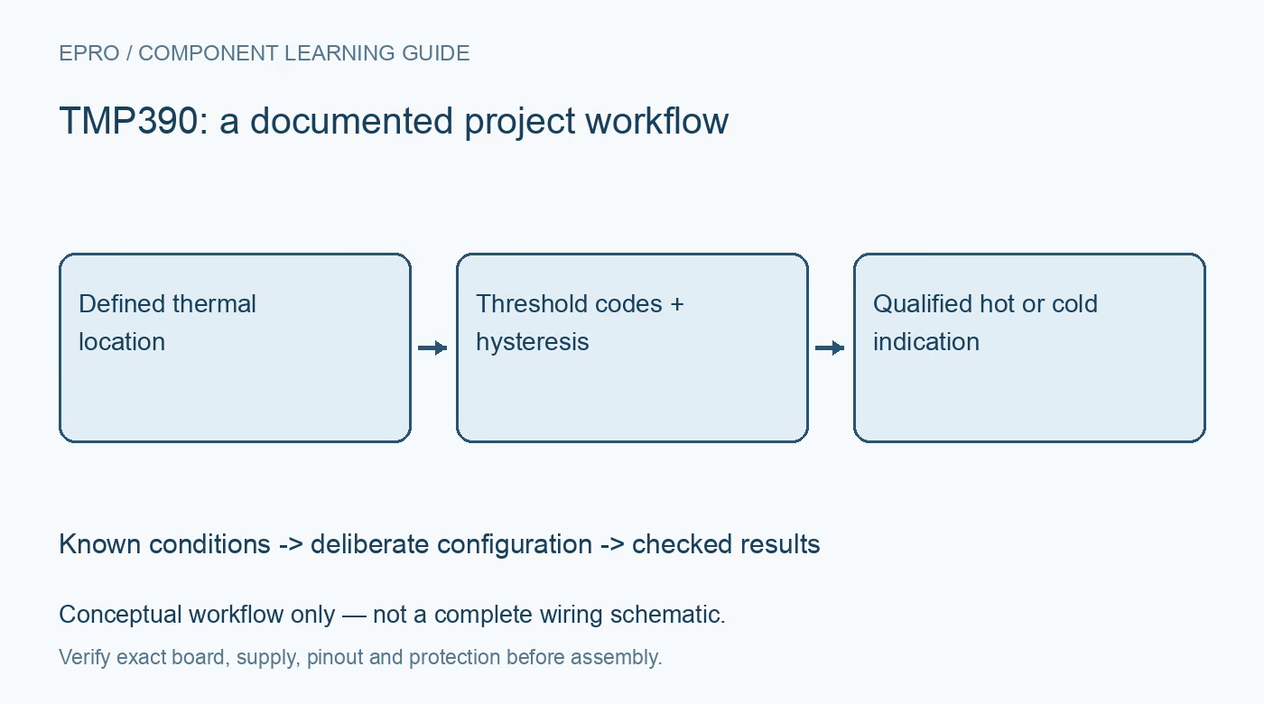
Configure TMP390 hot and cold thresholds with the correct resistor codes, hysteresis and output interpretation; distinguish trip testing from calibration. This is a documentation-based planning guide, not a report of independent hands-on testing.
1. Recognize a threshold switch rather than a thermometer
TMP390 provides hot and cold switching outputs, not a numerical temperature register. Define the physical location whose temperature matters and the action each output should request. Confirm the exact device and accuracy grade, supply range, package and board connections. A digital output can indicate a threshold event without reporting the actual temperature. If the application needs logged numerical readings as well as a protective indication, plan an appropriate additional measurement path rather than inventing data from the switch state. Manufacturer documentation.
2. Select resistor codes from the correct table
The SETA and SETB resistor values select documented internal threshold and hysteresis options. Channel A covers hot thresholds in the specified two-degree steps, while channel B covers cold thresholds in five-degree steps. Use the actual table row for the intended channel and hysteresis, not interpolation between resistance values. These resistors encode choices; they do not form an unrestricted analog temperature adjustment. Check tolerance, assembly value and pin-to-ground connection against the valid code band for the selected setting. Manufacturer documentation.
3. Respect power-on capture and special pin states
The device determines the resistor-programmed settings after power-on and retains them until another power cycle. Changing a resistor while powered is therefore not a supported way to demonstrate a new threshold. Grounded or floating pins can have special behavior; consult the documented rules instead of assuming an absent resistor simply disables an output harmlessly. Record startup settings and verify the assembled components before energizing. Re-run the relevant checks after changing configuration components or the supply sequence. Manufacturer documentation.
4. Write separate trip and release conditions
A hot threshold trips as temperature rises and releases only after the applicable lower reset boundary is reached. The cold channel has the opposite direction, with its reset above the cold threshold. Include hysteresis explicitly in the system state table so firmware does not interpret persistence as a stuck output. The special single-channel configuration has its own conditions and must not be generalized to the ordinary two-channel setup. Use the datasheet tables to document the exact boundaries selected. Manufacturer documentation.
Newest in the store


5. Check open-drain outputs and observation timing
The outputs are open drain, so the pull-up rail, resistor and receiving input thresholds belong in the design. Verify active-state polarity and the behavior when the pull-up or sensor supply is absent. The sampling period also limits how rapidly a changing thermal condition can become an output transition. Do not treat a polled logic state as an instantaneous precision measurement. Include host polling, filtering and any downstream actuation delay in the thermal-response assessment for the actual assembly. Manufacturer documentation.
6. Use trip test only for its documented purpose
The manufacturer describes trip test as an assembly or production check of the device and output path, with specific SET pin logic levels and a single-toggle procedure under non-tripping thermal conditions. It is not intended as a normal functional control feature. Follow the allowed procedure without overriding the configuration network outside its limits. A forced output response does not establish temperature accuracy, thermal coupling or a calibrated threshold. Keep electrical trip-test evidence separate from controlled thermal qualification. Manufacturer documentation.
7. Validate the assembled thermal decision
Compare normal output transitions against an appropriate reference under controlled, safe temperature changes and sufficient stabilization time. Record the board location, enclosure, airflow, selected codes, hysteresis and accuracy grade. The device senses its local temperature, which can differ from a remote component or surrounding air. Check both trip and release behavior rather than only one transition. This planning guide does not establish suitability as a sole safety mechanism; evaluate system protection requirements independently for the actual application. Manufacturer documentation.
Related reading: TMP112 Temperature Sensor: 7 Checks for the Right Data Format.
Catalog note: The exact-part search did not return a matching Epro listing during preparation. Check the current catalog; this guide makes no price, availability or included-accessory claim.