


DRV8889-Q1 Stepper Driver: 7 Checks Before Trusting Stall Detection

DRV8889-Q1 Stepper Driver: 7 Checks Before Trusting Stall Detection
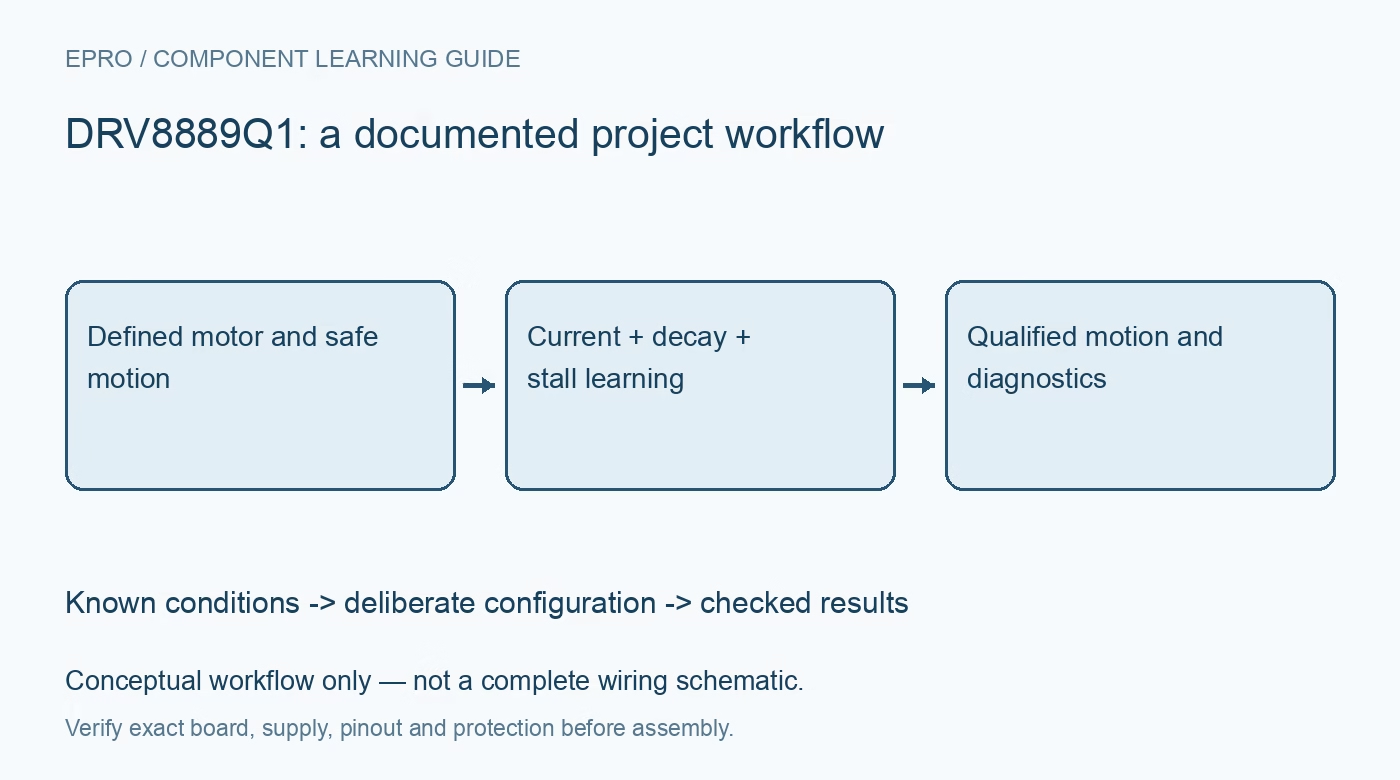
Configure DRV8889-Q1 stepping, winding current, decay mode and stall learning deliberately before using a diagnostic flag to infer mechanical motion. This is a documentation-based planning guide, not a report of independent hands-on testing.
1. Identify the driver, board and winding connections
Confirm the full DRV8889-Q1 or DRV8889A-Q1 variant, package and breakout schematic before applying power. Identify the two motor winding pairs and the mechanical travel that can be exercised safely. Disconnect power before changing motor wiring, restrain the mechanism appropriately and provide a practical stop method. A stepper driver’s phase-current rating is not a guarantee that an arbitrary motor or board can operate continuously at that value. Include supply, cooling and wiring in the review. Manufacturer documentation.
2. Establish current regulation before demanding motion
The driver integrates current sensing and uses VREF and torque settings to establish the winding-current command. Apply the relevant equations and register definitions for the exact device instead of copying a setting from another motor driver. Begin with conservative current and bounded motion. Check the winding and board thermal limits, and distinguish full-scale current from peak protection behavior. Successful SPI communication does not prove the power stage is configured or that the selected current is appropriate for the mechanism. Manufacturer documentation.
3. Keep STEP and DIR timing independent of SPI setup
Motion commands use the STEP and DIR interface, while SPI configures behavior and exposes diagnostics. Verify microstep mode, direction setup and hold timing, pulse widths and startup state at the actual pins. Increasing microstep resolution changes the number of commanded increments; it does not establish equivalent mechanical positioning accuracy. Save the motion profile and register configuration together. If the mechanism does not move, inspect enable, sleep, current regulation and winding connections before simply increasing the step frequency. Manufacturer documentation.
4. Use the decay mode required by stall detection
The documented stall algorithm requires smart tune Ripple Control decay mode and explicit stall-detection enable. It is not a universal flag that works identically in every decay setting. Confirm the relevant control bits by readback and keep the selected mode with the motion configuration. Other decay options can change winding-current behavior, noise and settling. A controller that writes only a stall threshold without establishing the supported mode has not completed the prerequisites for interpreting the diagnostic result. Manufacturer documentation.
Newest in the store


5. Learn or set a threshold under representative conditions
The manufacturer’s learning procedure requires a deliberately stalled motor under controlled conditions; an unloaded run is not equivalent. Use an appropriate safe fixture and the documented procedure, or defer learning if the mechanism cannot be restrained safely. Check the completion-success indication rather than assuming the initial threshold is qualified. The learned threshold is speed-dependent and may require relearning when speed changes. It is an application setting, not a calibrated torque measurement, absolute position reference or substitute for independent travel protection. Manufacturer documentation.
6. Distinguish stall, open load and protection faults
Read detailed status rather than mapping every nFAULT assertion to mechanical stall. Open-load detection and overcurrent protection have their own enabling conditions, latching and recovery policies. The datasheet also discusses open-load indications at electrical positions where a coil current is zero. Preserve relevant status before issuing a clear command, and use the proper readback interpretation for the exact variant. Repeatedly clearing a fault without investigating its cause can conceal a wiring, thermal or configuration problem. Manufacturer documentation.
7. Validate diagnostics without relying on them for safe travel
Exercise bounded, controlled motion with independent observation of the mechanism and a safe stop arrangement. Log commanded steps, speed, current setting, decay mode, learning result and diagnostic status. Do not deliberately drive an unprotected mechanism into a damaging obstruction to demonstrate stall detection. Assess the operating window and false indications through an appropriate safe test plan. This guide describes manufacturer-based configuration checks, not independent motion testing, and does not establish the diagnostic as a sole safety or homing mechanism. Manufacturer documentation.
Related reading: DRV8213 Motor Driver: 7 Checks Before Trusting Stall Detection.
Catalog note: The exact-part search did not return a matching Epro listing during preparation. Check the current catalog; this guide makes no price, availability or included-accessory claim.