


TPS2663 eFuse: 7 Checks for External FETs and Power Limiting

TPS2663 eFuse: 7 Checks for External FETs and Power Limiting
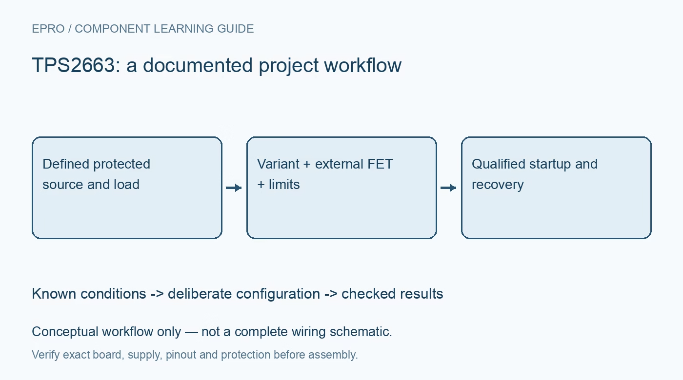
Plan a TPS2663 protected power path by checking the exact variant, external reverse-blocking FET, power limit, startup demand and recovery policy. This is a documentation-based planning guide, not a report of independent hands-on testing.
1. Read the complete variant before selecting protection
TPS2663 describes a family with different overvoltage, pulse-current and output-power-limit options. The comparison table distinguishes adjustable cutoff variants from fixed clamp variants, and not every member includes adjustable power limiting. Record the complete orderable number and package before copying an application circuit. A family headline does not establish the installed device’s response. Write a requirements table covering voltage limits, sustained load, permitted startup demand and the intended recovery behavior before selecting configuration components. Manufacturer documentation.
2. Distinguish the internal switch from external reverse protection
The device includes a hot-swap FET, but the datasheet describes reverse-polarity protection and reverse-current blocking support using an external N-channel FET controlled through the B-FET arrangement. Do not claim that the internal switch alone implements every reverse-protection function. Follow the applicable external-FET orientation, ratings and gate-drive guidance. Review all return and alternate power paths as well: another cable or energized downstream rail can change the system behavior even when the main protected path is designed correctly. Manufacturer documentation.
3. Keep operating voltage and surge claims separate
The recommended input operating range is 4.5 V to 60 V, while absolute maximum and transient conditions are separate specifications. Industrial surge-related features do not establish compliance for an arbitrary assembled board, enclosure or wiring arrangement. Begin qualification with a protected, current-limited low-voltage setup and bounded loads. High-energy surge or fault testing requires an appropriate laboratory and qualified personnel. Do not use this guide to construct improvised surge generators, defeat upstream protection or substitute an absolute maximum for a normal operating point. Manufacturer documentation.
4. Coordinate current and power limits by variant
Set the current-limit network from the documented procedure and include tolerance, thermal conditions and the capacity of the connectors and PCB. For variants with PLIM, distinguish output power limiting from a fixed output-current limit: the operating constraint changes with output voltage. Check whether the chosen suffix supports pulse overloads and under what conditions. A permitted transient does not become a continuous load rating. Preserve the applicable equations and comparison-table row alongside the selected resistor values. Manufacturer documentation.
Newest in the store


5. Assess capacitive startup and thermal regulation
Output capacitance, slew-rate control and downstream startup activity determine the initial demand. The datasheet describes charging behavior that can involve thermal regulation; that does not eliminate the need to evaluate startup duration and dissipation. Test normal startup with a representative load using a bounded source, observing input, output and temperature together. Avoid repeatedly increasing limits until a problematic load starts. First determine whether capacitance, load sequencing or the selected device envelope is responsible for the behavior. Manufacturer documentation.
6. Assign monitoring and recovery signals explicit meanings
The MODE setting selects documented fault-response behavior, including automatic retry or latch-off policies. Decide which response is appropriate for the system and how the host should react. PGOOD, fault indication and the analog current monitor serve different purposes and have electrical limits and scaling requirements. A ready signal does not certify the whole power path. Record pull-up supplies, monitor loading and the applicable reset procedure so firmware does not repeatedly restart an unresolved fault or misread a disconnected signal. Manufacturer documentation.
7. Preserve a safe qualification record
Document the exact variant, external FET, configuration network, source capability, load and board revision. Verify normal enable, startup, shutdown and permitted recovery transitions before attaching valuable downstream hardware. Keep observed current-monitor scaling and rail behavior separate from any compliance or certification claim. This documentation-based guide does not report independent fault testing. Reassess protection whenever an alternate supply, connector, external FET or load changes; a successful earlier power-up is not evidence for a revised system. Manufacturer documentation.
Related reading: TPS25947 eFuse: 7 Checks for Variant, Inrush and Fault Policy.
Catalog note: The exact-part search did not return a matching Epro listing during preparation. Check the current catalog; this guide makes no price, availability or included-accessory claim.