


LM27762 Dual Rails: 7 Checks for Headroom, Enables and PGOOD

LM27762 Dual Rails: 7 Checks for Headroom, Enables and PGOOD
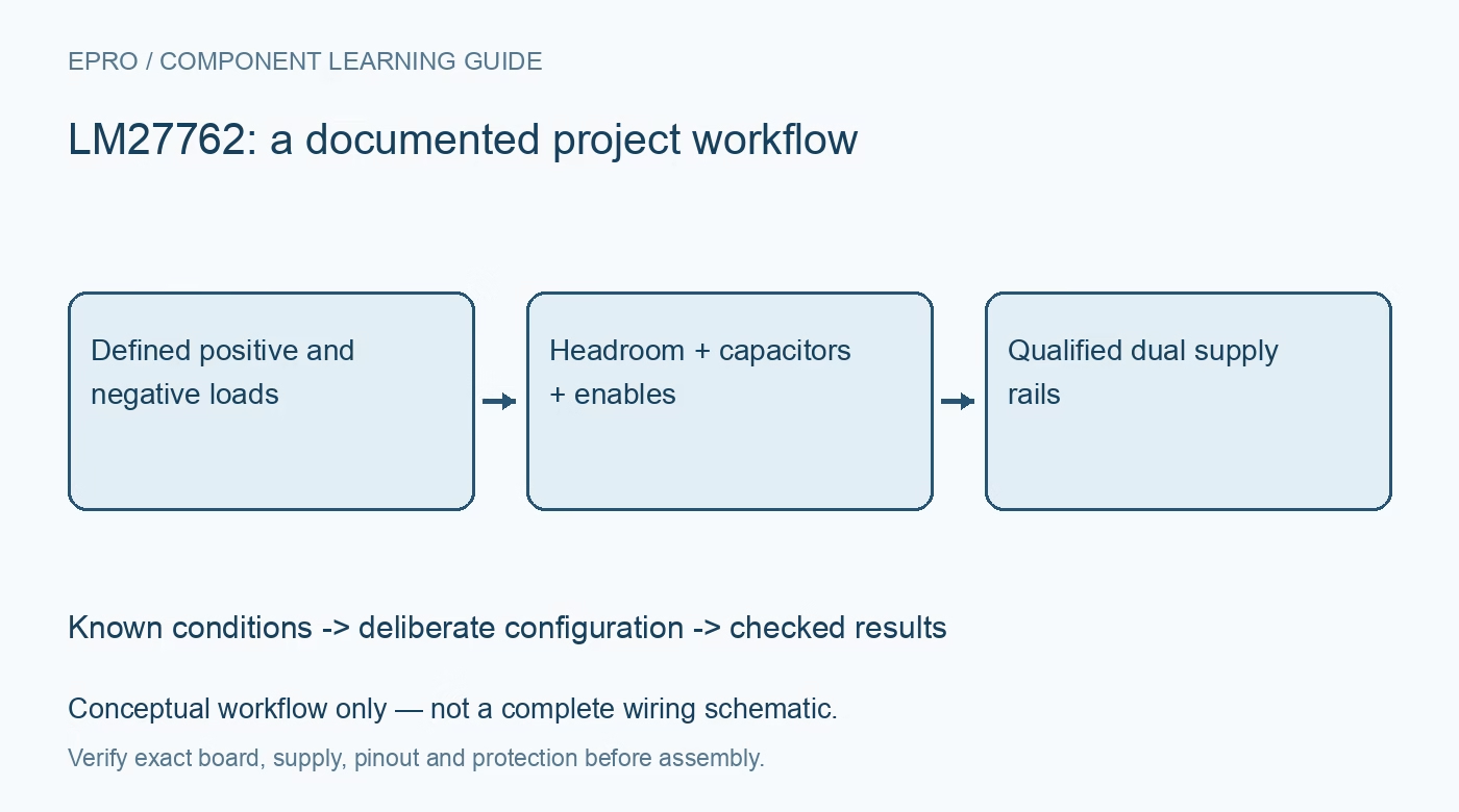
Plan LM27762 positive and negative rails by checking topology, load-dependent headroom, capacitors, independent enables and active-low power good. This is a documentation-based planning guide, not a report of independent hands-on testing.
1. Start with the actual dual-rail topology
LM27762 combines an inverting charge pump and negative LDO with a positive LDO supplied from the input. It is not a pair of independent boost converters. Define both rail voltages, load currents and startup requirements before using the advertised adjustment ranges. The positive output needs input headroom, and the negative output depends on charge-pump behavior plus its regulator. A nominal pair of requested voltages does not establish that both are achievable at the chosen input and load. Manufacturer documentation.
2. Check headroom at the lowest input voltage
The recommended input range is 2.7 V to 5.5 V, while the listed positive and negative output adjustment ranges have operating conditions. Do not infer that a low input can produce any arbitrary pair up to plus and minus 5 V. Account for load-dependent charge-pump loss and LDO dropout using the applicable curves and specifications. Include input ripple and wiring drop. Check each rail at its intended current rather than borrowing an unloaded result from the other channel. Manufacturer documentation.
3. Design feedback for each rail with correct polarity
Use the manufacturer’s positive and negative feedback equations and reference connections. The negative regulator’s network must not be treated as a positive-rail divider with minus signs added informally. Verify resistor placement, tolerance and the actual feedback node against the package pinout. Keep sensitive feedback routes away from switched charge-pump currents. Before attaching valuable analog circuitry, confirm both output polarities and voltages using a current-limited source and a bounded test load appropriate to the design. Manufacturer documentation.
4. Follow flying-capacitor and output-capacitor guidance
The inverting pump relies on its specified capacitor network, including the flying capacitor and associated return paths. Select effective capacitance and component characteristics using the application guidance, accounting for tolerance and voltage dependence. Short, deliberate current loops matter for ripple and interference. Replacing the recommended arrangement with an arbitrary reservoir is not a supported shortcut. Measure ripple with suitable probing under representative loads, and distinguish a probing artifact from actual rail noise before drawing conclusions about analog performance. Manufacturer documentation.
Newest in the store


5. Coordinate independent enables with the attached circuit
EN+ controls the positive LDO, while EN− controls the negative charge pump and LDO. Independent control can support sequencing, but the connected amplifier or converter may not tolerate every one-rail state. Review downstream input voltages and power-sequencing requirements before choosing delays. Disabled outputs have documented return paths toward ground, not instantaneous ideal discharge. Observe ordinary startup and shutdown at both rails, and prevent externally driven signals from creating unintended current paths through a partly powered load. Manufacturer documentation.
6. Decode the active-low power-good indication
PGOOD is an open-drain output whose documented logic zero means power good; this is opposite to many active-high ready conventions. Provide a suitable pull-up and verify the full truth conditions for enabled and disabled rails in the datasheet. Do not rename the signal in firmware without preserving its polarity. Monitor both output voltages during qualification rather than relying solely on one logic bit. A correct PGOOD level does not independently establish ripple, downstream settling or system readiness. Manufacturer documentation.
7. Qualify simultaneous loading and thermal behavior
The headline output-current capability is conditional, not a promise that every board can continuously supply the largest load on both rails at every voltage. Evaluate dissipation, source capability and effective headroom with the actual simultaneous loads. Record positive and negative voltage, ripple, startup, shutdown and temperature conditions. Avoid interpreting one satisfactory rail as evidence for the other. This documentation-based guide defines a verification plan rather than reporting bench results, and does not replace a thermal or downstream safety assessment for the complete assembly. Manufacturer documentation.
Related reading: TPS63810 Buck-Boost: 7 Checks for Safe Voltage-Preset Changes.
Catalog note: The exact-part search did not return a matching Epro listing during preparation. Check the current catalog; this guide makes no price, availability or included-accessory claim.