


TPS63810 Buck-Boost: 7 Checks for Safe Voltage-Preset Changes

TPS63810 Buck-Boost: 7 Checks for Safe Voltage-Preset Changes
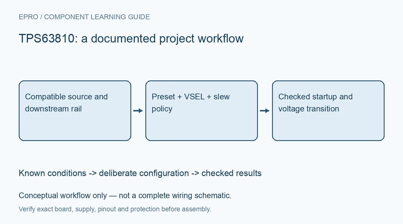
Plan TPS63810 output presets around the exact variant, I2C startup, VSEL selection, transition rate and real load limits before changing a powered rail. This is a documentation-based planning guide, not a report of independent hands-on testing.
1. Separate the device variants before startup
Confirm whether the assembly uses TPS63810 or TPS63811 and inspect its actual supporting components. Their initial output-programming requirements differ: the TPS63810 has preprogrammed output presets, while the TPS63811 requires the documented programming sequence before startup. Do not assume a board powers up at the last value written by another application. Build a startup table showing the expected output, enable state, selector state and host availability for the exact fitted device. Manufacturer documentation.
2. Check the entire input and output envelope
The converter operates within a low-voltage input range and offers a programmable output range, but neither statement guarantees a particular load current everywhere in that space. Evaluate the selected input, output, inductor and thermal arrangement together. Include source resistance, battery discharge and startup current in the budget. Headline output-current capability is conditional. Keep the first tests current limited, and disconnect sensitive downstream electronics until the programmed voltage and startup behavior are confirmed. Manufacturer documentation.
3. Define both output presets explicitly
The two output-voltage registers are selected through VSEL. Document which selector level maps to each programmed value and what establishes that level before firmware starts. Read back both registers after configuration rather than checking only the currently selected one. A later VSEL edge can expose an overlooked preset. Compare both values against the absolute and recommended limits of every downstream component, including devices that remain connected while their own supply or reset state changes. Manufacturer documentation.
4. Treat a voltage change as a controlled transition
The configured slew behavior governs transitions between output settings. Choose a transition policy that suits the downstream load and then inspect the resulting rail during both upward and downward changes. A programmed target alone does not prove that the rail reaches it without an unacceptable transient or delay. Include load current, output capacitance and pre-existing voltage in the test conditions. Log the selector command and the observed settling interval separately. Manufacturer documentation.
Newest in the store


5. Make I2C initialization resilient
The device has a documented I2C address and initialization requirements. Follow the recommendation for a STOP condition after initial pull-up-supply power-up, rather than assuming that a host reset leaves every bus participant in a clean transaction state. Check pull-up voltages and communication availability while the converter is disabled or changing state. Define a bounded retry policy and safe behavior after failed configuration. Do not enable a sensitive load solely because an address scan returned a response. Manufacturer documentation.
6. Review mode and reverse-current behavior
Choose power-save or forced-PWM behavior for the application instead of accepting a library default without review. The operating mode affects ripple, efficiency and current behavior at light load. This converter can support forward and reverse current in active operation; it is not a universal reverse-blocking element. Shutdown load disconnection is a separate behavior. Review prebiased-output and source interactions before connecting another powered rail or a load that can return energy. Manufacturer documentation.
7. Save startup and load-transition evidence
Capture input voltage, output voltage, relevant control states and load conditions for startup, both preset transitions, shutdown and recovery after a supply interruption. Verify which settings survive each event and which must be restored. Repeat at representative source and load extremes within the approved operating envelope. Keep configuration bytes and waveform conditions with the project record. The finished result should establish an acceptable transition policy for that assembly, not imply a universal rating for every breakout board. Manufacturer documentation.
Related reading: TPS63802 Buck-Boost: 7 Checks Across the Battery Range.
Catalog note: The exact-part search did not return a matching Epro listing during preparation. Check the current catalog; this guide makes no price, availability or included-accessory claim.