


TPS63802 Buck-Boost: 7 Checks Across the Battery Range

TPS63802 Buck-Boost: 7 Checks Across the Battery Range
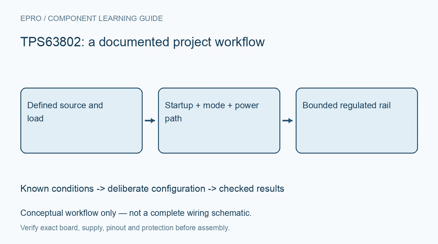
Plan a TPS63802 buck-boost rail with startup headroom, realistic load capability, deliberate mode selection and documented layout and transient checks. This is a documentation-based planning guide, not a report of independent hands-on testing.
1. Define the TPS63802 operating envelope
TPS63802 is a buck-boost converter intended to regulate when the source can be above, near or below the output. Specify the full source-voltage range, load profile and required output before selecting components. Do not reduce the design brief to a single nominal battery voltage. The expected behavior near a depleted source, during load bursts and around the buck-to-boost region matters as much as a convenient midrange bench condition. Manufacturer documentation.
2. Distinguish startup from continued operation
The documented minimum input for startup is not the same as the lower voltage at which an already operating converter can continue under specified conditions. Review both requirements for the exact source and load. A circuit that runs after starting from a stronger supply has not demonstrated cold startup from a weak battery. Include source impedance, connector drop and inrush in the assessment rather than assuming that an unloaded terminal voltage describes the voltage available during startup. Manufacturer documentation.
3. Evaluate output capability at each condition
Available output current depends on input voltage, output voltage, efficiency, current limits and thermal conditions. Do not read a headline current figure as an unconditional guarantee across the complete range. In boost operation, the source current can be greater than the output current. Check whether the source, inductor and board can support that demand. Keep protective current limiting in the evaluation setup and avoid using a device protection event as the normal operating point. Manufacturer documentation.
4. Select passive components from the design guidance
Use the manufacturer procedure for the feedback divider, inductor and capacitors. Account for inductor saturation and losses, capacitor voltage rating and effective capacitance under bias. A nominal part value alone does not establish suitability. Follow the placement and routing guidance for switching current paths and feedback. A solderless breadboard or long jumper construction is not equivalent to the recommended compact layout for evaluating a switching regulator with meaningful noise and transient expectations. Manufacturer documentation.
Newest in the store


5. Choose the light-load operating mode deliberately
Review the documented power-save and forced-PWM behavior and decide which is appropriate for the application. Noise-sensitive acquisition and long idle periods can create different priorities. Preserve the selected mode when comparing observations. A no-load quiescent-current specification does not establish complete battery life, and a waveform taken in one mode does not describe the other. Evaluate the regulator together with its actual sensor or processor load rather than judging it from an unloaded voltage display. Manufacturer documentation.
6. Include enable and prebiased-output behavior
Review the documented enable, shutdown, load-disconnect and prebiased-output behavior in the complete power tree. Identify any other source that can drive the output and analyze that path explicitly. Do not connect supplies together merely because the converter supports a particular operating feature. Define the application safe state during startup and removal of power. Independent safeguards are still required where an unintended output level or reverse power path could damage a connected device. Manufacturer documentation.
7. Validate transitions with appropriate instrumentation
Plan controlled observations of startup, relevant source changes and bounded load steps using suitable measurement practices. Record probe arrangement, bandwidth, source impedance and load conditions alongside results. Do not claim efficiency or ripple performance from an ordinary unloaded multimeter reading. The linked buck-boost selection guide provides broader context, not a completed TPS63802 design. This documentation-based article proposes an evaluation boundary and makes no assertion that a physical converter has been independently tested across the battery range. Manufacturer documentation.
Related reading: Buck Boost Converter: 7 Checks Before Choosing.
Catalog note: The exact-part search did not return a matching Epro listing during preparation. Check the current catalog; this guide makes no price, availability or included-accessory claim.