


LDC1612 Inductive Sensor: 7 Checks Before Reporting Distance

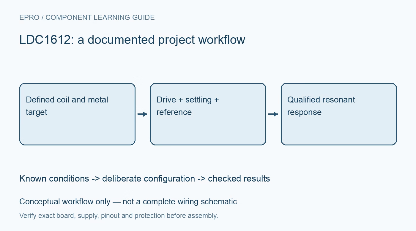
LDC1612 Inductive Sensor: 7 Checks Before Reporting Distance
Plan LDC1612 inductive sensing around the actual resonant coil, target geometry, reference clock, drive settings and coherent 28-bit results. This is a documentation-based planning guide, not a report of independent hands-on testing.
1. Define what the LDC1612 measures
LDC1612 is a two-channel inductance-to-digital converter that observes a resonant sensing arrangement. It does not directly return a universal distance in millimeters. Target material, size, orientation and coil geometry influence the response. Begin with a documented coil and target assembly and define the intended mechanical change. A related magnetometer measures a different physical quantity; magnetic-field or compass examples should not be mistaken for interchangeable inductive position-sensing methods. Manufacturer documentation.
2. Identify the exact channel and device family
The shared documentation includes devices with different channel counts and resolutions. Confirm LDC1612 identity, carrier wiring, supply and logic compatibility before using a generic family library. Record the selected channel and interface address. A successful I2C read is only an electrical communication check. It does not prove that the resonator is oscillating correctly, that the channel configuration matches the installed coil or that the host is decoding the result from the intended channel. Manufacturer documentation.
3. Design the resonant sensor deliberately
Choose the sensing coil and capacitor using the manufacturer frequency and sensor-design guidance. Include component tolerance, quality factor and the actual target conditions in the assessment. Keep connections and nearby conductive structures in the assembly record because they can affect response. Do not treat a coil photograph as an electrical specification. A meaningful evaluation begins with a resonator inside the documented operating envelope, not an arbitrary winding that happens to produce changing digital values. Manufacturer documentation.
4. Set drive and settling for the installed sensor
Review the documented sensor-drive arrangement and amplitude requirements for the actual resonator. Select or evaluate the appropriate drive settings rather than assuming a copied maximum is harmless or beneficial. Configure settling behavior so conversion begins under the intended sensor condition. An inadequately established oscillation can create data problems that software averaging will not solve. Preserve channel settings with the coil revision, and reassess after changes to sensor components, cabling or mechanical installation. Manufacturer documentation.
Newest in the store


5. Make the reference clock part of the model
The conversion relates sensor behavior to the configured reference clock and divider arrangement. Confirm whether the internal or external reference is used and document its relevant characteristics. Apply the manufacturer relationship for the selected settings rather than labeling the raw number as inductance or distance. A stable-looking digital result does not by itself establish an accurate physical scale. Clock configuration and sensor design must remain associated with the data used for later calibration or comparison. Manufacturer documentation.
6. Read coherent results and inspect error information
Assemble the documented multiregister result in the required order and distinguish measurement bits from status or error information. Review freshness and channel identification when alternating acquisitions. Do not concatenate words from unrelated updates or silently accept a flagged sensor condition as an ordinary sample. Preserve raw register values during evaluation. This makes it possible to separate data-framing mistakes, stale observations and resonator operating problems before adding a distance model or a polished graphical display. Manufacturer documentation.
7. Calibrate the mechanical relationship explicitly
Establish any position relationship using known, controlled target conditions and retain the target material, geometry and temperature context. A curve obtained for one assembly should not be advertised as universal. Assess environmental drift and whether a reference channel is appropriate for the design. The related LIS3MDL guide is a contrast in sensing principles, not a compatible calibration method. This LDC1612 workflow proposes traceable resonant-response checks and claims no independent distance accuracy, universal sensing range or finished-product validation. Manufacturer documentation.
Related reading: LIS3MDL Magnetometer: 7 Checks Before Compass Heading.
Catalog note: The exact-part search did not return a matching Epro listing during preparation. Check the current catalog; this guide makes no price, availability or included-accessory claim.