


LIS3MDL Magnetometer: 7 Checks Before Compass Heading

LIS3MDL Magnetometer: 7 Checks Before Compass Heading
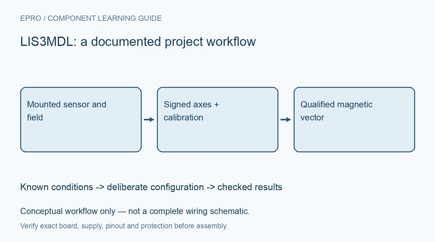
Build a LIS3MDL magnetic-data record with coherent signed axes, matching sensitivity, assembly-aware calibration and explicit compass-heading limits. This is a documentation-based planning guide, not a report of independent hands-on testing.
1. Define the LIS3MDL output honestly
LIS3MDL measures a three-axis magnetic field. A compass heading is a derived application result, not a ready-made guarantee attached to those three numbers. Decide first whether the project needs raw magnetic logging, field-change detection or orientation-related information. Record the sensor axes relative to the assembly. Without that coordinate description, even correctly decoded data can produce a mirrored, rotated or otherwise misleading heading when passed into a generic compass formula. Manufacturer documentation.
2. Confirm the exact interface and board
The device supports I2C and SPI, but the exact carrier determines how the relevant pins and configuration are exposed. Verify supply and logic compatibility, pull-ups where applicable and the selected interface connections. Use device identification and documented register access as early checks. Do not assume a library for another magnetometer is compatible because both return three axes. Similar product photographs and a familiar bus address are not a substitute for identifying the silicon. Manufacturer documentation.
3. Pair full scale with the correct sensitivity
Select the full-scale range and operating configuration deliberately, then apply the sensitivity corresponding to that selection. A raw signed code cannot be converted consistently if software assumes a different range from the hardware. Keep units explicit throughout the processing chain. Include the selected performance and timing settings in the configuration record so later changes do not silently alter the meaning or cadence of stored magnetic data used for comparison or calibration. Manufacturer documentation.
4. Preserve coherent signed axis data
Read the documented multibyte axis output using the correct byte order and signed interpretation. Use the available data-ready and overrun information to distinguish a fresh coherent vector from an incomplete or overwritten acquisition. Review the device’s data-update controls for the chosen read sequence. Polling faster is not a cure for mixed samples. Preserve raw axes and relevant status when debugging so scaling errors can be separated from acquisition-timing or register-framing problems. Manufacturer documentation.
Newest in the store


5. Assess magnetic interference after assembly
Keep the sensor away from magnets, motors, high-current paths and ferromagnetic hardware where practical. Then assess the actual enclosure rather than relying only on a bare-board observation. Hard-iron offsets and soft-iron distortion are different effects. The documented offset facilities do not replace a complete calibration model for every installation. Record the calibration method and assembly state, and reassess after moving hardware that changes the field environment around the sensor. Manufacturer documentation.
6. Distinguish self-test from compass calibration
The documented self-test applies an internal stimulus and checks the sensor response under specified conditions. It does not remove enclosure distortion, establish geographic alignment or certify heading accuracy. Follow the manufacturer procedure and acceptance limits if using it, then restore the intended measurement configuration. For heading, also consider tilt compensation, axis conventions and the appropriate magnetic declination. A horizontal two-axis calculation is not automatically valid when the assembly is tilted or dynamically moving. Manufacturer documentation.
7. Store the vector before trusting the heading
Retain raw and scaled axes, range, status, calibration revision and assembly orientation with evaluation data. Flag readings outside the validated conditions instead of smoothing every disturbance into a believable compass display. The linked QMC5883L article illustrates another sensor’s acquisition concerns, not matching registers or sensitivities. A credible LIS3MDL project separates electrical communication, magnetic calibration and heading interpretation, and makes no claim of independently measured compass accuracy merely because a numerical direction appears on screen. Manufacturer documentation.
Related reading: QMC5883L Arduino: Raw-Axis Checks Before Compass Heading.
Catalog note: The exact-part search did not return a matching Epro listing during preparation. Check the current catalog; this guide makes no price, availability or included-accessory claim.