


TPS65133 Dual Supply: 7 Checks for Fixed Rails and Startup Order

TPS65133 Dual Supply: 7 Checks for Fixed Rails and Startup Order
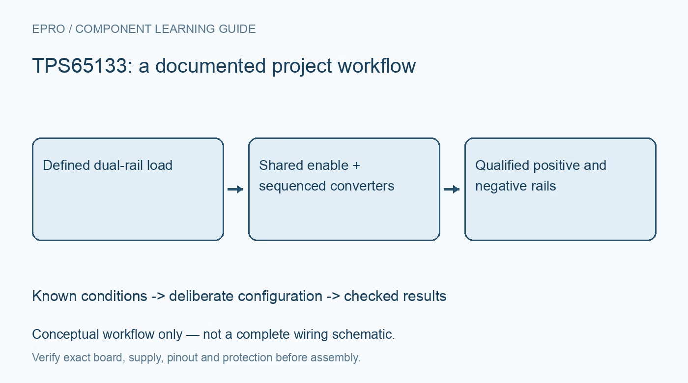
Plan TPS65133 fixed plus and minus 5 V rails with the correct converter topology, shared enable, sequenced startup, loading and discharge behavior. This is a documentation-based planning guide, not a report of independent hands-on testing.
1. Recognize fixed outputs and the two converter types
TPS65133 provides fixed positive 5 V and negative 5 V outputs. The positive rail uses a boost converter, while the negative rail uses an inverting buck-boost converter. It is not the same topology as a positive LDO paired with an inverting charge pump, and its outputs are not adjusted with arbitrary feedback dividers. Confirm the actual part and board schematic. Document required current, ripple tolerance and startup requirements for each downstream circuit before selecting the supply arrangement. Manufacturer documentation.
2. Check the input envelope and simultaneous power demand
The recommended input range is 2.9 V to 5.0 V, with output-current capability subject to the specified operating conditions and thermal design. Calculate the combined output power and allow for losses when assessing source current. A battery or upstream regulator must support both channels and their startup demands. Do not infer an arbitrary high-current capability from a single unloaded rail. Review source droop, connector resistance and input capacitance at the lowest intended input voltage as well as the nominal point. Manufacturer documentation.
3. Follow the two-inductor application arrangement
Select the inductors and input and output capacitors according to the manufacturer design procedure, including saturation, ripple current and effective capacitance. Keep switching loops compact and follow the recommended grounding and exposed-pad connections. Positive and negative switching nodes must not be mistaken for rail outputs during probing or wiring. Begin with bounded loads and a current-limited source. A schematic with the correct nominal inductance still requires appropriate component ratings and a layout that manages the actual switched currents. Manufacturer documentation.
4. Treat the shared enable and startup order as system behavior
The device has one EN input controlling both converters, not independent positive and negative enable pins. The positive rail starts first; the negative converter begins approximately two milliseconds after the positive output reaches its specified level. This documented sequence means the downstream circuit can experience a temporary positive-only supply. Check whether attached amplifiers, sensors or externally driven inputs tolerate that condition. Do not describe independently operating converters as independently programmable startup sequencing when the actual enable arrangement is shared. Manufacturer documentation.
Newest in the store


5. Evaluate unequal loads without assuming unlimited independence
The datasheet supports a full mismatch between positive and negative output currents within the individual channel capabilities. That does not remove the shared input-power and thermal constraints or the startup relationship. Test the actual asymmetric load combinations, including one lightly loaded rail and the other near its intended demand. Observe both outputs during each transition. A satisfactory balanced-load result may not reveal the behavior of the real analog circuit, whose current can change differently on the two supplies. Manufacturer documentation.
6. Account for active discharge and protection recovery
Both outputs have documented active-discharge behavior when disabled, with operation dependent on the remaining input supply. Do not promise instantaneous or unconditional return to zero after unplugging power. The datasheet distinguishes startup short behavior from normal-operation fault detection and describes shutdown and recovery conditions. Use those rules in the system plan without deliberately creating destructive faults. Monitor both rails before releasing downstream reset or reconnecting external signals, and investigate an unexpected shutdown instead of repeatedly toggling enable. Manufacturer documentation.
7. Qualify the downstream circuit across power transitions
Record rail rise and fall, relative timing, ripple, input current and temperature with representative positive and negative loads. Check ordinary enable, disable and source-ramp behavior using suitable instrumentation and safe probing. Preserve component values, layout revision and the downstream sequencing requirements with the results. A pair of steady-state meter readings does not establish that startup is harmless or that analog settling is complete. This documentation-based guide defines verification work and does not claim independent dual-supply measurements. Manufacturer documentation.
Related reading: LM27762 Dual Rails: 7 Checks for Headroom, Enables and PGOOD.
Catalog note: The exact-part search did not return a matching Epro listing during preparation. Check the current catalog; this guide makes no price, availability or included-accessory claim.