


TPS61023 Boost Converter: 7 Checks for Cold Start and Pass-Through

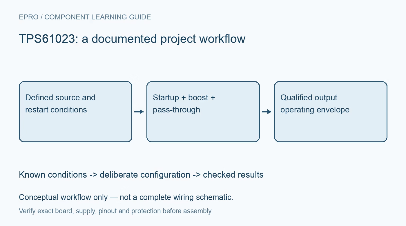
TPS61023 Boost Converter: 7 Checks for Cold Start and Pass-Through
Plan TPS61023 operation by separating 1.8 V startup from low-voltage running, switch-current limits, pass-through behavior and output loading. This is a documentation-based planning guide, not a report of independent hands-on testing.
1. Separate a boost converter from a buck-boost function
TPS61023 is a synchronous boost converter, with an output-setting range and operating conditions defined in its datasheet. It does not provide arbitrary step-down regulation when the input rises above the requested output. Confirm the exact board, inductor, feedback network and load before planning battery operation. Record the full input trajectory, including initial connection, normal discharge, shutdown and restart. A design that works during one part of a battery discharge may behave differently after the same battery has already fallen to a low voltage. Manufacturer documentation.
2. Distinguish cold start from continued low-voltage operation
The headline low input voltage is not the cold-start threshold. The device requires the documented approximately 1.8 V input condition to start; after startup and once the output is above 2.2 V, it can continue operating with input as low as 0.5 V under applicable conditions. Check what happens after disable, brownout or a fully discharged output. Do not promise that a deeply discharged source can independently restart the converter simply because it previously sustained an already-running system. Manufacturer documentation.
3. Translate switch-current limits into an output-power budget
The typical 3.7 A figure describes valley switch-current limiting, not a universal 3.7 A output capability. Boost conversion draws more input current as input voltage falls for a given output power, with losses adding to demand. Evaluate inductor saturation, ripple, source resistance, PCB heating and load transients using the applicable design guidance. A tiny converter board can reach thermal or component limits well before an attractive headline suggests. Check the intended load across the complete operating input range. Manufacturer documentation.
4. Select feedback and energy-storage components deliberately
Calculate the output divider using the manufacturer equation and keep the feedback path quiet. Select the inductor and input and output capacitors for actual current, effective capacitance and voltage conditions, not merely matching nominal values in a photograph. Compact switching loops and suitable returns matter for ripple and stability. Begin with a current-limited source and bounded load. A correct unloaded output voltage is only an initial check, not proof that the source and storage components can support startup or transient demand. Manufacturer documentation.
Newest in the store


5. Review pass-through when input exceeds the target
When the input is above the selected output, the documented pass-through behavior allows the output to follow the source minus the relevant path drop. This is not regulation down to the programmed boost target. Check the maximum voltage the downstream circuit can tolerate, including a fresh battery or alternate external source. Overvoltage protection is a device protection feature with its own conditions, not a substitute for selecting a topology that meets the load’s normal supply requirements. Manufacturer documentation.
6. Account for mode changes and shutdown without assumptions
Switching behavior changes with input voltage and light-load demand, affecting ripple, spectral content and efficiency. Use the applicable operating curves rather than applying one switching-frequency figure to the entire input range. Shutdown disconnects the main input-to-output path under the documented conditions, but stored output energy and externally driven interfaces still need review. Keep EN at a defined level and evaluate normal turn-on and turn-off with the actual load. True disconnection is not the same as instantaneous output discharge. Manufacturer documentation.
7. Test the restart envelope as well as steady operation
Qualify normal cold start, continued discharge operation, disable and restart with representative source impedance and loads. Record input voltage at the converter, output voltage, current, temperature, capacitance and enable timing. If restart fails after deep discharge, investigate the specified startup conditions rather than increasing load limits or presenting the event as unexplained firmware behavior. This guide defines manufacturer-based verification checks, not independent power-converter measurements. Reassess the startup and pass-through envelope whenever the battery, load or power-control policy changes. Manufacturer documentation.
Related reading: TPS63020 Buck-Boost: 7 Checks for Switch Current and PG Meaning.
Catalog note: The exact-part search did not return a matching Epro listing during preparation. Check the current catalog; this guide makes no price, availability or included-accessory claim.