


INA821 Instrumentation Amplifier: 7 Checks for Gain and Common Mode

INA821 Instrumentation Amplifier: 7 Checks for Gain and Common Mode
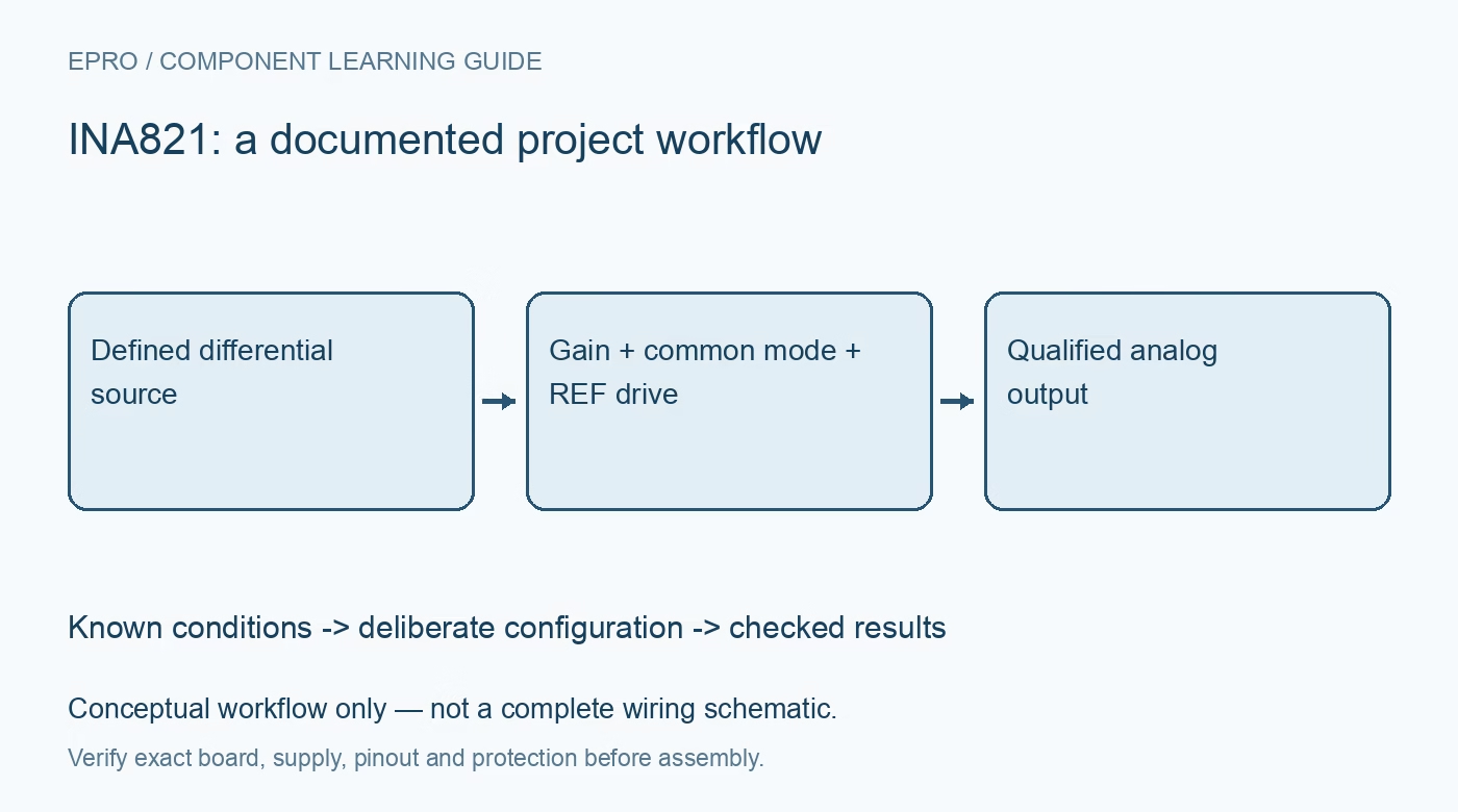
Plan an INA821 instrumentation-amplifier stage with the correct gain resistor, bias-current paths, REF drive and input common-mode versus output headroom. This is a documentation-based planning guide, not a report of independent hands-on testing.
1. Define the small signal and its large background voltage
INA821 amplifies a differential input while rejecting common-mode voltage, but rejection does not make arbitrary input voltages legal. Record both input voltages relative to the supply rails, their difference, source impedance and expected transients. Choose the single or dual supply from the recommended operating conditions. The advertised input-protection capability is not a precision operating range. A bridge with a modest differential output may still exceed the amplifier operating envelope through its common-mode level. Manufacturer documentation.
2. Use the INA821 gain constant rather than a family shortcut
For INA821 the gain equation is G = 1 + 49.4 kOhm / RG. The nearby INA826 or other instrumentation-amplifier family is not a substitute source for this constant or pin numbering. For example, nominal gain 100 uses approximately 499 Ohm. Include resistor tolerance, temperature coefficient and connection resistance when estimating accuracy. Leaving the gain terminals open gives the documented unity-gain configuration; do not short them as though they were unused logic inputs. Manufacturer documentation.
3. Verify the common-mode versus output operating region
The allowed input common-mode range depends on supply voltage, gain and demanded output voltage. Use the manufacturer operating-region plots rather than checking input and output limits independently. Calculate the positive and negative signal extremes around REF, then verify both ends of the proposed range. Internal input-stage saturation can occur before the external output seems obviously out of bounds. Clipping that appears only at one bridge excitation level often deserves this check before software calibration. Manufacturer documentation.
4. Give both inputs a defined bias-current return path
High input impedance does not mean zero input bias current. Floating sources, AC coupling and transformer connections need deliberate return paths for both amplifier inputs. Without them the inputs can drift outside the common-mode range and saturate. Choose return resistors with the source impedance, noise and balance requirements in mind; a single arbitrary resistor may degrade rejection. Document where the bias current returns, particularly if a sensor connector can be unplugged during operation. Manufacturer documentation.
Newest in the store


5. Drive REF as an analog summing reference
REF sets the output baseline, so noise and impedance at this terminal affect the measurement. Provide the low-impedance reference connection described in the datasheet; do not assume a weak resistor divider is an ideal midrail source. Check reference startup, bypassing and the available output swing around it. If an ADC shares the reference network, include its loading and sampling behavior. An apparently accurate offset correction in firmware cannot restore headroom lost to a badly chosen baseline. Manufacturer documentation.
6. Budget bandwidth and settling at the selected gain
The device bandwidth changes with gain; the unity-gain headline is not the bandwidth at gain 100 or 1000. Check signal bandwidth, interference filtering and settling before the ADC sampling instant. Keep bypass capacitors close to the supply pins and route the gain resistor compactly. Evaluate the actual output capacitance and cable load. A stable output on a handheld meter is not sufficient evidence that a multiplexed acquisition system receives fully settled samples. Manufacturer documentation.
7. Validate with differential and common-mode checks separately
Begin with protected, low-voltage bench signals rather than live industrial or physiological connections. Apply a small known differential input, vary the common-mode level only within the verified range, and record the output against the predicted gain and REF. Include input-short offset and source-disconnection behavior. Save supply settings, resistor values, load and instrument uncertainty. Describe results as board-specific measurements only after performing them; the datasheet-based checks here do not constitute independent validation or safety certification. Manufacturer documentation.
Related reading: INA826 Instrumentation Amplifier: 7 Checks for REF and Gain Headroom.
Catalog note: The exact-part search did not return a matching Epro listing during preparation. Check the current catalog; this guide makes no price, availability or included-accessory claim.