


TPS62160 Buck Converter: 7 Checks for Power-Good Interpretation

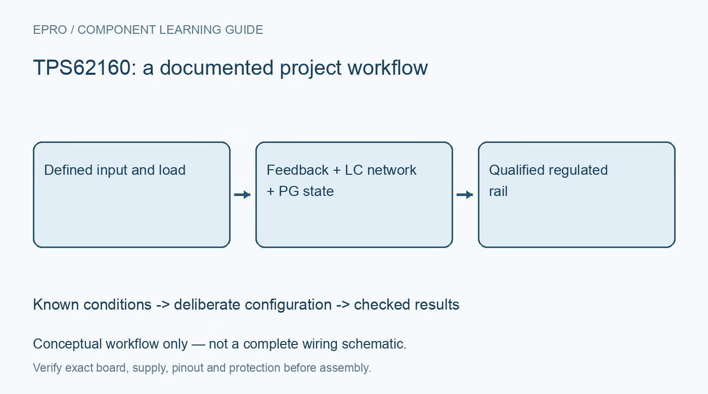
TPS62160 Buck Converter: 7 Checks for Power-Good Interpretation
Plan a TPS62160 buck supply with correct sensing, component selection, startup checks and power-good logic that does not mistake shutdown for readiness. This is a documentation-based planning guide, not a report of independent hands-on testing.
1. Identify the adjustable device and supply envelope
TPS62160 is the adjustable member of a synchronous step-down family, not a boost converter or a universal regulator module. The documented input range is 3 V to 17 V, with up to 1 A output under suitable electrical and thermal conditions. Record the actual package, programmed output, minimum source voltage and worst-case load before choosing components. A family application circuit showing a fixed-output sibling is not automatically the right feedback circuit for the adjustable part. Manufacturer documentation.
2. Treat feedback and output sensing as separate responsibilities
Review both FB and VOS connections against the exact pin-function table and reference layout. The divider programs the adjustable output; output sensing must observe the intended rail rather than an arbitrary noisy switching node. Route sensitive feedback away from SW and high-current loops. Include divider tolerance and ground error in the output budget. A correct nominal resistor ratio cannot compensate for a disconnected sensing pin, excessive trace pickup or a mistaken package orientation. Manufacturer documentation.
3. Select the inductor and capacitors as a control network
Use the datasheet component-selection and stability guidance, not just an inductor with the right printed inductance. Check saturation current, ripple current, winding loss and the effective capacitance remaining under DC bias. Evaluate the inductance and output capacitance together because they shape the control-loop response. Account for ceramic tolerance and temperature. Keep the input capacitor near the switching power path; a large capacitor at a distant bench supply does not replace local bypassing. Manufacturer documentation.
4. Do not equate a high PG level with an enabled regulator
PG is an open-drain indicator requiring a compatible pull-up. Crucially, the datasheet specifies a high-impedance PG state when the converter is disabled by EN, undervoltage lockout or thermal shutdown. A pull-up can therefore produce a high logic level while the output is not ready. Qualify PG with the intended operating state and, where appropriate, an independent output check. Define what downstream firmware should do during shutdown rather than interpreting every high level as permission to start. Manufacturer documentation.
Newest in the store


5. Distinguish light-load behavior from dropout
Automatic power-save operation changes switching activity at small loads; sparse switching is not by itself evidence of failure. Near the input-output boundary, 100% duty-cycle operation reduces dropout but does not generate a voltage above the source. Source resistance, switch resistance and inductor loss still matter. Check regulation at the lowest expected input under load. Avoid concluding that a no-load measurement proves the rail can support the application throughout battery discharge. Manufacturer documentation.
6. Bring up with controlled loads and observable startup
Start with a current-limited source and a noncritical load, after checking polarity and soldering with power removed. Observe input voltage, output ramp, enable and PG together. Increase the load in bounded steps while recording steady-state voltage and transient recovery. Use safe probing practices to avoid shorting adjacent pins or switching nodes. If the source limit repeatedly engages, separate input-capacitor charging from sustained overload before raising the limit or replacing components. Manufacturer documentation.
7. Release the rail only with a documented readiness rule
Record the schematic revision, divider, inductor, capacitor types, pull-up rail and accepted startup timing. Include the load range, source range and measurement bandwidth in the test record. State explicitly how readiness distinguishes disabled, starting, regulating and faulted conditions. This guide supplies a documentation-based review path, not measured performance for an untested board. Use manufacturer limits and application-specific tests to approve the final assembly, especially where several downstream rails depend on PG sequencing. Manufacturer documentation.
Related reading: TPS62040 Buck Converter: 7 Checks for Light-Load Voltage Positioning.
Catalog note: The exact-part search did not return a matching Epro listing during preparation. Check the current catalog; this guide makes no price, availability or included-accessory claim.