


ADS7953 Multiplexed ADC: 7 Checks for Channel Frames and Range

ADS7953 Multiplexed ADC: 7 Checks for Channel Frames and Range
Read ADS7953 data with verified channel identity, manual or automatic sequence timing, input-range scaling and the correct multiplexer-to-ADC signal path. This is a documentation-based planning guide, not a report of independent hands-on testing.
1. Resolve sixteen channels and twelve-bit coding
ADS7953 is the sixteen-channel twelve-bit member of a wider pin-compatible ADC family. Other members differ in channel count or resolution, so confirm the exact device and package before using a shared driver. GPIO availability also depends on package. Build a physical channel map with allowed voltage range and source impedance for every input. A family schematic or a sixteen-bit SPI word does not establish that all sixteen received bits are conversion data. Manufacturer documentation.
2. Connect the multiplexer and ADC path intentionally
The device exposes the multiplexer output and ADC input arrangement so the analog signal path can include the documented direct connection or suitable buffering. Follow the application guidance rather than assuming that every necessary path is hidden inside the package. Evaluate source impedance and settling after channel changes, especially when adjacent channels have different voltages. Verify the assembled routing and any buffer before running a sequence. Correct digital addressing cannot repair an unconnected or inadequately driven analog path. Manufacturer documentation.
3. Track reference and selected input range
The device supports documented unipolar ranges based on the external reference, including the one-times and two-times reference options. Check the reference drive, supply constraints and individual pin limits; selecting a larger range does not authorize a voltage beyond the analog supply’s permitted input envelope. Preserve range state with each channel’s scaling. A valid conversion word interpreted with the wrong range can produce a plausible voltage that is systematically wrong, even when the reference itself is stable. Manufacturer documentation.
4. Map commands, acquisition and returned channel identity
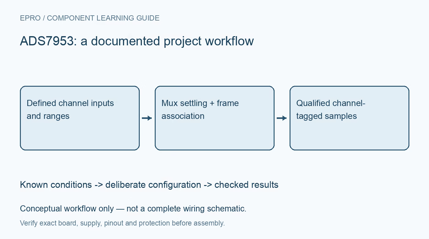
Manual channel commands, multiplexer selection, acquisition and output data occur at defined points across successive frames. Follow the timing diagram rather than treating a word returned while sending a channel command as that command’s immediate measurement. Maintain explicit frame association in the driver. Verify it with distinct bounded levels on several channels. The family’s zero-latency description must not be expanded into a claim that software channel selection, analog settling and serial readout all happen instantaneously in one arbitrary transaction. Manufacturer documentation.
Newest in the store


5. Parse the address field or configured GPIO substitute
The normal sixteen-bit output contains a four-bit channel address followed by twelve conversion bits. The documented GPIO-status option can replace the address field, so the parser must know the active format. Do not sign-extend the entire output or interpret the upper nibble as analog magnitude. Verify channel identity against the physical inputs during bring-up. Keep raw words and expected frame state so an off-by-one sequence error is not hidden by reasonable-looking values from another channel. Manufacturer documentation.
6. Qualify automatic sequencing and alarm configuration
The automatic modes have distinct setup and channel-sequence rules. Establish the desired sequence and range behavior using the applicable control format, then verify actual returned identities instead of assuming channels advance as the software array does. Alarm settings and GPIO functions have their own configuration implications. A threshold flag does not establish correct wiring or lossless acquisition. Include the time available to settle each source at the intended throughput and retain mode changes as explicit acquisition boundaries. Manufacturer documentation.
7. Validate channel transitions, not just static inputs
Compare results for known inputs with representative voltage differences between successive channels and the actual sequence rate. Record reference, range, source network, buffer, frame timing, mode and channel-identity checks. Inspect clipping and incorrect associations separately from noise or gain error. A single channel measured slowly does not qualify a fast multiplexed scan. This guide is documentation-based, not independent converter characterization; repeat the settling and frame-mapping checks after changing channel order, source impedance, host timing or input range. Manufacturer documentation.
Related reading: ADS7038 ADC: 7 Checks for Channel Identity, Averaging and CRC.
Catalog note: The exact-part search did not return a matching Epro listing during preparation. Check the current catalog; this guide makes no price, availability or included-accessory claim.