


TMP110 I2C Sensor: 7 Checks for Variant Pins and Data Format

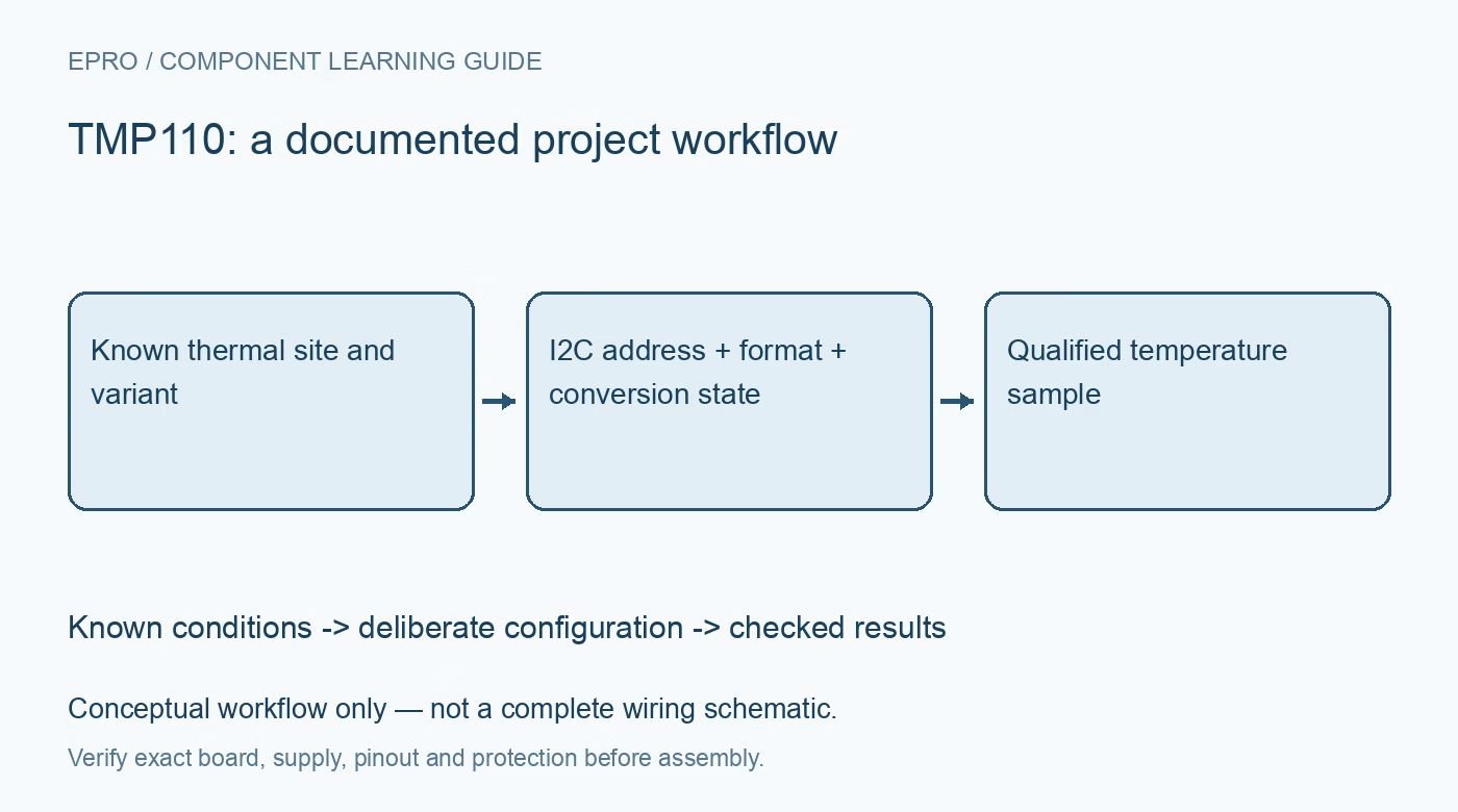
TMP110 I2C Sensor: 7 Checks for Variant Pins and Data Format
Review TMP110 address and alert variants, twelve- or thirteen-bit temperature decoding, conversion freshness and one-shot timing before trusting an I2C value. This is a documentation-based planning guide, not a report of independent hands-on testing.
1. Identify what the fifth package pin actually does
TMP110 uses an exceptionally small five-pin package, but its fifth pin is not identical across all orderable variants. TMP110D uses an address-selection pin, while the D0 through D3 alert variants provide an alert output with fixed address choices. Verify the order code, pin-function table and footprint together. A generic TMP110 symbol can conceal this distinction. Do not add an address strap to a pin that is an output on the fitted device, or expect an alert signal from an address-only variant. Manufacturer documentation.
2. Plan bus voltage and address from the documented variant
The device operates from a documented 1.14 V to 5.5 V supply range, but the host and pull-ups must still satisfy the interface electrical requirements. Derive the I2C address from the exact alert variant or address-pin connection rather than assuming a single family address. Check whether other devices already occupy that address. Mixed-bus coexistence wording does not make the part a native I3C target with every I3C feature; implement the actual supported interface and timing. Manufacturer documentation.
3. Decode the selected temperature format rather than raw bytes
The default result format contains twelve signed temperature bits; extended mode uses thirteen. The code step remains 0.0625 degrees Celsius, while field position and sign extension must match the selected format. Extract the appropriate field before interpreting it as twos complement. The documentation identifies a format indication in the second byte that can help distinguish modes. Test positive and negative examples and retain the configuration with each acquisition; a generic signed-sixteen-bit scaling rule is not automatically correct. Manufacturer documentation.
4. Distinguish code resolution from thermal accuracy
A small temperature code step does not imply accuracy of that same size. Use the manufacturer accuracy limits over the intended temperature range and include the reference instrument and mounting effects in comparisons. The chip senses its own temperature, influenced by the board and nearby heat sources. Place it where the desired thermal condition can reach the package, and allow time for equilibrium. Avoid presenting a CPU-adjacent board reading as ambient air temperature without an appropriate thermal design and validation. Manufacturer documentation.
Newest in the store


5. Track conversion completion and startup freshness
Following power-up or reset, the temperature register can read zero until the first conversion completes. Repeated I2C reads do not themselves create new measurements. Use the configured continuous conversion period or the documented one-shot sequence to establish when a sample is fresh. The active conversion duration and standby interval are different quantities, so polling rate alone does not define update rate. Mark startup and timed-out acquisitions invalid instead of treating a plausible zero as a trustworthy observation. Manufacturer documentation.
6. Handle one-shot and alert operation as separate state machines
A one-shot request initiates a conversion and subsequently returns the sensor to shutdown under the documented behavior. A repeated request during an active conversion does not restart that conversion. Follow the ready-status or timing rules before accepting the result. For alert-equipped variants, configure thresholds, polarity and operating mode according to the register definitions, and provide the required pull-up. An alert event and a newly read temperature are related but not interchangeable records, especially around threshold crossings or delayed host servicing. Manufacturer documentation.
7. Validate variant identification and recovery in firmware
Record the actual order code, address, format mode, conversion policy and threshold settings. Test cold start, negative-temperature decoding with known code vectors, shutdown recovery and interrupted bus transactions. Compare stable measurements with a suitable reference after allowing the board to equilibrate. If a related sensor driver is reused, review compatibility field by field rather than relying on a marketing family statement. This guide is derived from manufacturer documentation and does not claim independent calibration or suitability for safety-critical thermal protection. Manufacturer documentation.
Related reading: TMP125 SPI Sensor: 7 Checks for Ten-Bit Data and Shutdown.
Catalog note: The exact-part search did not return a matching Epro listing during preparation. Check the current catalog; this guide makes no price, availability or included-accessory claim.