


TCA9538 GPIO Expander: 7 Checks for Reset and Floating Inputs

TCA9538 GPIO Expander: 7 Checks for Reset and Floating Inputs
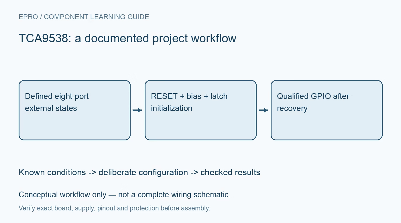
Plan TCA9538 GPIO startup and recovery with its reset pin, absent internal port pull-ups, output-latch defaults and change-based interrupt behavior. This is a documentation-based planning guide, not a report of independent hands-on testing.
1. Check the reset-capable eight-bit device and address
TCA9538 provides eight GPIO lines through I2C or SMBus and includes two hardware address pins plus an active-low RESET input. It is not a pin-for-pin substitute for every sixteen-pin expander. Verify the footprint, hardware address and supply against the actual device. The manufacturer supports standard and fast I2C speeds, so set the bus accordingly. An address acknowledgement does not prove that external loads will see safe levels when the host or expander resets. Manufacturer documentation.
2. Provide external bias where an input must not float
The manufacturer distinguishes TCA9538 from TCA9554 by removing the internal port pull-up resistors, replacing an address function with RESET and changing the address range. Do not transfer the TCA9554 weak-pull-up assumption into this design. Buttons, disconnected connectors and unused inputs may need deliberate external bias. Choose resistor values from noise immunity, leakage, power and signal-source requirements. A high-impedance input can appear stable during a bench check while still being uncontrolled under real wiring and environmental conditions. Manufacturer documentation.
3. Define the electrical state during RESET assertion
RESET can restore register and interface defaults while the device supply remains present. Follow its minimum pulse width, release timing and pull-up requirements from the datasheet. Because default direction is input, external circuitry rather than the old output command determines a released port during reset. Review what attached enables or reset lines do in that interval. A reset intended to recover I2C communication must not inadvertently energize a load or let a critical control line drift to an unsafe level. Manufacturer documentation.
4. Reinitialize the output latch before enabling output drivers
The default output register is high, while the configuration register initially makes the ports inputs. Preload the desired latch state before selecting output direction if a low level is required at startup. After a hardware reset, discard any software assumption that the previous register contents survived. Reapply output data, input inversion and direction in an explicit order. Masked updates need a trustworthy software shadow or controlled register read, particularly when more than one task can modify the same port byte. Manufacturer documentation.
Newest in the store


5. Read pin state and output command for different purposes
The Output Port register shows the requested latch setting; the Input Port register observes incoming logic levels. They are not redundant confirmations of identical electrical behavior. A pin driven high may not reach a valid high voltage if overloaded or shorted. Check individual and package-wide current limits and provide external drivers for larger or inductive loads. Polarity inversion affects the reported input sense as documented, not the physical output transistor arrangement or its ability to source current. Manufacturer documentation.
6. Service interrupts without assuming every edge is stored
INT is an open-drain change indication associated with inputs, requiring a suitable pull-up. Reading the input register or a return to the reference state can clear the condition, and the datasheet describes an acknowledge interval in which changes can be lost or very short. Do not use this interface as an exact high-speed pulse counter. Debounce switches, re-read levels as appropriate, and use hardware capture for events that must never be missed. Direction changes can also affect the interrupt state. Manufacturer documentation.
7. Test bus recovery with real external control loads
Exercise host reset, expander RESET, supply cycling and an interrupted bus operation with noncritical loads first. Confirm that input bias, output-latch initialization and interrupt handling lead to the intended physical states throughout recovery. Save direction, output and inversion masks with the wiring documentation. Verify pull-up rails remain compatible during partial power conditions. This article provides a manufacturer-based recovery checklist, not independent evidence of isolation, machine safety or high-current control capability for an assembled system. Manufacturer documentation.
Related reading: TCA9554 GPIO Expander: 7 Checks for Pull-Ups and Interrupts.
Catalog note: The exact-part search did not return a matching Epro listing during preparation. Check the current catalog; this guide makes no price, availability or included-accessory claim.