


TPS7A02 Nanopower LDO: 7 Checks Beyond Quiescent Current

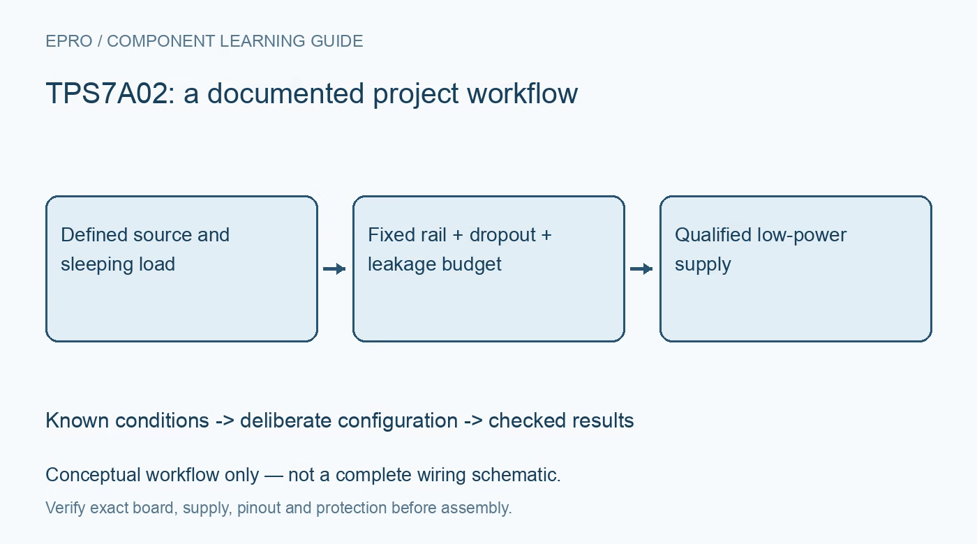
TPS7A02 Nanopower LDO: 7 Checks Beyond Quiescent Current
Plan a TPS7A02 low-power rail with the correct fixed-output variant, dropout budget, effective capacitance, smart enable and reverse-current precautions. This is a documentation-based planning guide, not a report of independent hands-on testing.
1. Confirm the output-voltage code and package
TPS7A02 is a fixed-output low-dropout regulator family, not an adjustable buck converter. Orderable output voltage and package details matter, especially with very small footprints and several available options. Match the fitted marking to the bill of materials before checking the rail. The documented input range is 1.5 V to 6 V and the output current capability reaches 200 mA under suitable conditions. A family-wide list of output voltages is not a promise that every board can be reprogrammed to any of them. Manufacturer documentation.
2. Keep quiescent current separate from total battery current
The headline 25 nA quiescent current is a typical device condition, not the current consumed by a complete powered sensor board. Add load current, enable-network current, reference circuitry, leakage and any always-on indicators. The regulator uses adaptive and dynamic biasing, so current can change with load and transients. Use the appropriate datasheet curves and limits instead of assuming the headline value at every instant. A realistic energy budget follows the full operating and sleep duty cycle. Manufacturer documentation.
3. Budget dropout at the actual load and temperature
The output cannot remain regulated when the input lacks sufficient headroom. Dropout depends on output current and operating conditions, so a single no-load measurement does not establish the minimum battery voltage. Include cell resistance and pulse-load droop when evaluating end-of-discharge operation. The family maintains low quiescent current even in dropout, but low self-consumption does not imply a regulated output in that state. Check the downstream brownout threshold separately from the regulator minimum input rating. Manufacturer documentation.
4. Choose capacitors by effective value and stability limits
The manufacturer calls for appropriate local input and output capacitors and specifies effective output-capacitance conditions for stability. Account for DC-bias derating, tolerance and temperature rather than relying on the printed nominal value. More capacitance is not unlimited permission: check the documented maximum as well as the minimum and startup behavior. Place bypassing close to the regulator and keep the load-return path sensible. A capacitor measured at zero bias may provide substantially less capacitance on the operating rail. Manufacturer documentation.
Newest in the store


5. Understand smart enable before adding external bias
The active-high enable includes a smart internal pulldown arrangement intended to keep a floating EN disabled while reducing current when enabled. Verify the actual thresholds and host voltage instead of assuming every low-power LDO treats an unconnected enable identically. If independent control is unnecessary, follow the documented EN connection. Include host startup, shutdown and partially powered conditions in the plan. An added resistor network can consume more current than the regulator quiescent headline, so justify it electrically and in the power budget. Manufacturer documentation.
6. Review discharge and reverse-current conditions separately
The family documentation describes active output discharge when disabled; confirm the exact orderable device and implementation. This is not blanket reverse-current protection. The datasheet explicitly warns about output-to-input current after the source collapses, especially with stored output charge. Check external circuits that can keep the output powered and avoid relying on discharge circuitry to absorb arbitrary energy. Provide suitable external measures where necessary. Do not infer that a disabled regulator safely tolerates every possible output voltage or capacitor arrangement. Manufacturer documentation.
7. Validate sleep current and pulse recovery with suitable instruments
Use a measurement method capable of resolving the intended standby current without introducing excessive burden voltage or leakage. Then separately test startup and bounded load pulses, since a slow current meter can conceal rail excursions. Record source voltage, effective capacitor choices, output code, enable state and environmental conditions. Measure board leakage and remove unrelated indicators before attributing current to the LDO alone. This documentation-based guide does not claim a measured battery lifetime or validated transient performance for an untested assembly. Manufacturer documentation.
Related reading: TPS7A20 Low-Noise LDO: 7 Checks for Headroom and Real PSRR.
Catalog note: The exact-part search did not return a matching Epro listing during preparation. Check the current catalog; this guide makes no price, availability or included-accessory claim.