


TPS7A20 Low-Noise LDO: 7 Checks for Headroom and Real PSRR

TPS7A20 Low-Noise LDO: 7 Checks for Headroom and Real PSRR
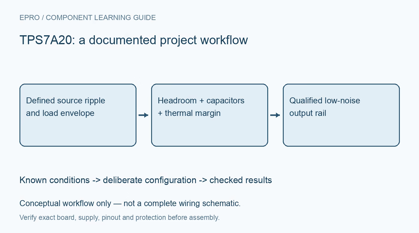
Plan a TPS7A20 supply around its output option, dropout margin, effective capacitance, thermal load and frequency-dependent rejection before powering analog loads. This is a documentation-based planning guide, not a report of independent hands-on testing.
1. Confirm the voltage option and package pinout
The TPS7A20 is supplied in defined output-voltage options and several packages. Confirm the complete ordering code and pin assignment before connecting a voltage-sensitive load. A related regulator footprint or a board label naming only the family does not establish the actual output setting. Record the intended supply and load range, including startup and shutdown conditions. This linear regulator does not provide the same voltage-conversion behavior as a buck-boost device used upstream in a power tree. Manufacturer documentation.
2. Budget dropout across the complete source range
The input must provide adequate headroom above the requested output for the intended current and temperature. A typical or single-condition dropout figure is not a universal guarantee across every operating point. Include battery discharge, source tolerance, cable resistance and ripple troughs in the calculation. Once the regulator approaches dropout, both regulation and rejection behavior change. A nominally correct bench input voltage can therefore hide a weak design if the real source later sags during a load transient. Manufacturer documentation.
3. Evaluate effective capacitance rather than the label alone
The regulator requires appropriate output capacitance for stable behavior, and input capacitance supports transient response and practical source impedance. Review the recommended operating conditions and capacitor guidance for the selected assembly. Ceramic capacitance changes with DC bias, temperature, tolerance and package. A component marked with the nominal recommended value may not retain that value in service. Include placement and return paths in the review instead of assuming that any distant capacitor on the same rail meets the local requirement. Manufacturer documentation.
4. Interpret PSRR as a frequency-dependent result
The headline power-supply rejection figure applies under specified conditions and at a particular frequency. It does not describe equal rejection of every switching harmonic, transient or broadband noise source. Compare the upstream ripple spectrum with the manufacturer curves at the intended headroom, load and capacitance. Choose a measurement bandwidth and probing method that can distinguish source ripple from pickup and instrument noise. The phrase low noise is not evidence that an arbitrary regulator-and-converter combination produces a quiet assembled rail. Manufacturer documentation.
Newest in the store


5. Check heat and load transients separately
Approximate load-related dissipation from the input-output voltage difference multiplied by output current, then include the full applicable thermal conditions and additional losses. Package and board layout affect the resulting junction temperature. The rated output current does not guarantee acceptable heat at every input voltage. Also inspect startup and fast load changes: a rail that meets a static meter reading can still dip or ring beyond a sensitive circuit’s tolerance. Keep steady-state and dynamic qualification as separate evidence. Manufacturer documentation.
6. Review enable, discharge and reverse-current conditions
The device provides controlled enable behavior and active output discharge, but those features do not make every shutdown arrangement safe. The manufacturer warns about reverse current when stored output charge remains after the input collapses. Evaluate alternate supplies, large output capacitance and connected interfaces before relying on the discharge path. Define host enable levels and power-state transitions using the documented limits. An output commanded off is not a universal reverse-blocked or galvanically isolated node. Manufacturer documentation.
7. Qualify the complete rail with its real analog load
Record input and output waveforms, current, capacitor choices, package, temperature and probing conditions across representative operating points. Include minimum source voltage, a load step, enable cycling and source removal with appropriate protection. Check noise over the application’s relevant bandwidth without claiming an instrument-limited trace proves zero noise. The completed result should establish usable regulation and noise performance for this source-load combination, not extend a datasheet headline into an unconditional promise for every PCB or operating condition. Manufacturer documentation.
Related reading: TPS63810 Buck-Boost: 7 Checks for Safe Voltage-Preset Changes.
Catalog note: The exact-part search did not return a matching Epro listing during preparation. Check the current catalog; this guide makes no price, availability or included-accessory claim.