


INA828 Instrumentation Amplifier: 7 Checks for ADC Interfacing

INA828 Instrumentation Amplifier: 7 Checks for ADC Interfacing
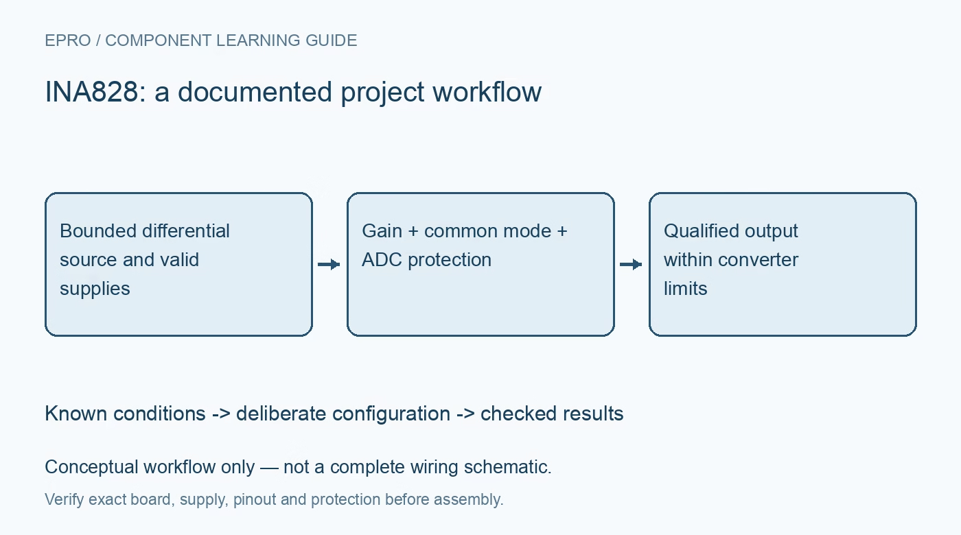
Review an INA828 analog front end around supply headroom, its 50-kilohm gain equation, protected inputs and a separately protected downstream ADC interface. This is a documentation-based planning guide, not a report of independent hands-on testing.
1. Match the amplifier supply to the actual device
The INA828 operates over a wider supply range than some low-voltage instrumentation amplifiers and has a documented minimum supply requirement. Do not power it from a typical 3.3-volt microcontroller rail simply because a related amplifier works there. Identify single- or dual-supply operation, local bypassing and the downstream ADC rail separately. A connector carrying a valid logic voltage is not evidence of a valid analog-amplifier supply. Keep the actual schematic and ordering code with the measurement configuration. Manufacturer documentation.
2. Use the INA828 gain equation rather than a family guess
Gain is established by an external resistor using G = 1 + 50000/RG when RG is in ohms. A resistor calculation copied from an instrumentation amplifier with a 100-kilohm gain constant produces a different result. Include resistor tolerance, sensor offset and the maximum differential signal in the output-range calculation. Check the documented gain dependence of bandwidth and other errors. Selecting a high gain is not a substitute for demonstrating that the complete input and output envelopes remain linear. Manufacturer documentation.
3. Check common-mode limits at the intended output
The usable input common-mode region depends on supply, gain and output conditions. Input protection and low differential amplitude do not remove those constraints. Evaluate the manufacturer operating-region guidance for the actual signal source and reference setting. A plausible output near midscale does not establish that all internal stages remain within their linear region. Include both signal extremes and expected common-mode movement in the review before accepting the amplifier as a front end for a precision converter. Manufacturer documentation.
4. Establish REF as an analog design choice
REF shifts the output baseline and therefore affects how a bipolar differential signal fits inside a single-supply ADC range. Use the required low-impedance connection and include reference accuracy and noise in the error budget. An unloaded divider reading the desired midpoint is not enough to establish suitable drive behavior. Check startup and reset states of any reference buffer as well as steady operation. An ADC midpoint established in firmware cannot correct an amplifier output that was already clipped or improperly referenced. Manufacturer documentation.
Newest in the store


5. Protect the ADC independently of the amplifier inputs
The amplifier’s protected input capability does not extend automatically to its output or to the ADC connected downstream. A supply fault or saturated amplifier can present a voltage outside a low-voltage converter’s allowed range. Review limiting, filtering and acquisition requirements using the ADC documentation and the actual output envelope. Include power-off cases where the amplifier remains energized while the converter is not. A successful nominal conversion is not proof that the interface is safe during startup, shutdown or a sensor fault. Manufacturer documentation.
6. Separate input survival from valid measurement
The manufacturer documents substantial input-overvoltage protection, but that is not a promise of accurate measurement throughout the protection range or permission to apply arbitrary energy. Check the complete pin, thermal and source conditions. Use bounded safe tests within the intended operating envelope during ordinary bring-up; any overload qualification needs an appropriately controlled procedure. Mark data invalid during saturation or abnormal input conditions and establish a recovery criterion rather than quietly treating the next plausible code as a calibrated observation. Manufacturer documentation.
7. Validate the chain from source to converter code
Begin with known safe differential inputs and representative common-mode levels. Record amplifier supplies, gain resistor, reference voltage, analog output and raw ADC code together. Exercise relevant signal extremes, host reset and a disconnected source, including the required bias-current return paths. Evaluate noise over the bandwidth the application actually uses. A useful handover distinguishes amplifier error, reference error, ADC scaling and protection behavior, without claiming that protected inputs or a single fitted calibration factor guarantee an accurate or universally safe measurement system. Manufacturer documentation.
Related reading: INA333 Instrumentation Amplifier: 7 Checks Before Raising Gain.
Catalog note: The exact-part search did not return a matching Epro listing during preparation. Check the current catalog; this guide makes no price, availability or included-accessory claim.