


SN74LVC1T45 Translator: 7 Checks for Direction and Power States

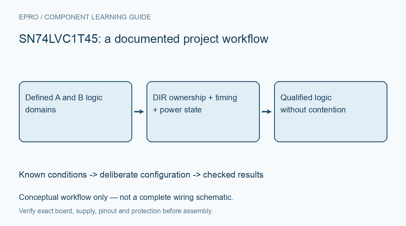
SN74LVC1T45 Translator: 7 Checks for Direction and Power States
Use SN74LVC1T45 with explicit DIR ownership, dual-rail thresholds, turnaround timing and partial-power rules rather than as an automatic I2C level shifter. This is a documentation-based planning guide, not a report of independent hands-on testing.
1. Choose a direction-controlled interface deliberately
The SN74LVC1T45 is a single-bit dual-supply transceiver with explicit direction control. It is not an automatic bidirectional analog switch or a generic I2C level-shifting circuit. Identify the protocol, driving endpoint and receiving endpoint before choosing it. A push-pull translator connected to an open-drain bus requires a different compatibility analysis from a purpose-built I2C repeater. Do not infer suitability from the fact that the supply voltages happen to match the two systems. Manufacturer documentation.
2. Reference each port to its own supply
The A port tracks VCCA and the B port tracks VCCB within their documented operating ranges. Check input thresholds and output guarantees for the actual translation pair, not merely absolute maximum ratings. Include the receiver’s requirements and load in that comparison. Record decoupling and the common ground arrangement. This device changes logic levels but does not provide galvanic isolation, eliminate ground differences or make long unconditioned cables behave like short PCB connections. Manufacturer documentation.
3. Drive DIR in the VCCA logic domain
The DIR input is referenced to VCCA. Confirm that the controlling host produces a valid low and high in that domain under the permitted input conditions. Assign a defined state during startup and reset rather than relying on a floating control input. Document which endpoint owns DIR and which data direction each level selects. A host on the B-side supply cannot automatically be assumed compatible with the control pin just because its data port is correctly translated. Manufacturer documentation.
4. Prevent both endpoints from driving during turnaround
Changing direction changes which port the transceiver drives. Follow the documented disabling, enabling and propagation timing when releasing one endpoint and activating the other. A direction bit write completing in software does not establish that the old output has already become high impedance. Use an explicit turnaround interval justified by the interface timing. Test the complete sequence under representative loads, since contention can exist briefly even when the steady-state truth table appears correct. Manufacturer documentation.
Newest in the store


5. Do not invent a separate output-enable control
The device’s six-pin arrangement does not provide an independent OE pin for arbitrary host-controlled disconnection. Plan bus ownership using the actual available functions rather than a driver template written for a larger translator. The input circuitry also needs defined logic levels; unused or undriven CMOS inputs can increase consumption or create unwanted behavior. Review both the data net and DIR across host resets. A receiver changing to input mode does not by itself establish a valid, nonfloating level. Manufacturer documentation.
6. Apply partial-power specifications to the stated conditions
The Ioff and supply-isolation features support specified powered-down conditions, including the documented behavior when either supply is at ground. Do not extend that description without review to every slowly collapsing, floating or partially energized rail. Check the actual supply sequence, signal levels and possible back-power paths. Keep the data and control limits separate. A feature designed to limit unwanted current during power loss is not evidence that all connected circuitry remains safe or that system power domains are fully isolated. Manufacturer documentation.
7. Validate logic at the real load and data rate
Measure or otherwise qualify low and high levels, propagation behavior, edge quality and direction changes with the actual endpoints and wiring. Use the timing specifications for the selected rail pair and load rather than a maximum-rate headline from another condition. Include reset, one-domain power loss and recovery in the test plan. Retain supply, DIR, endpoint mode and waveform conditions together. The completed record should demonstrate deliberate bus ownership and valid logic, not simply show continuity through a level-shifter module. Manufacturer documentation.
Related reading: TCA9617B I2C Repeater: 7 Checks for Compatible Buffered Lows.
Catalog note: The exact-part search did not return a matching Epro listing during preparation. Check the current catalog; this guide makes no price, availability or included-accessory claim.