


TPS62125 Buck Converter: 7 Checks for Enable Hysteresis and Storage

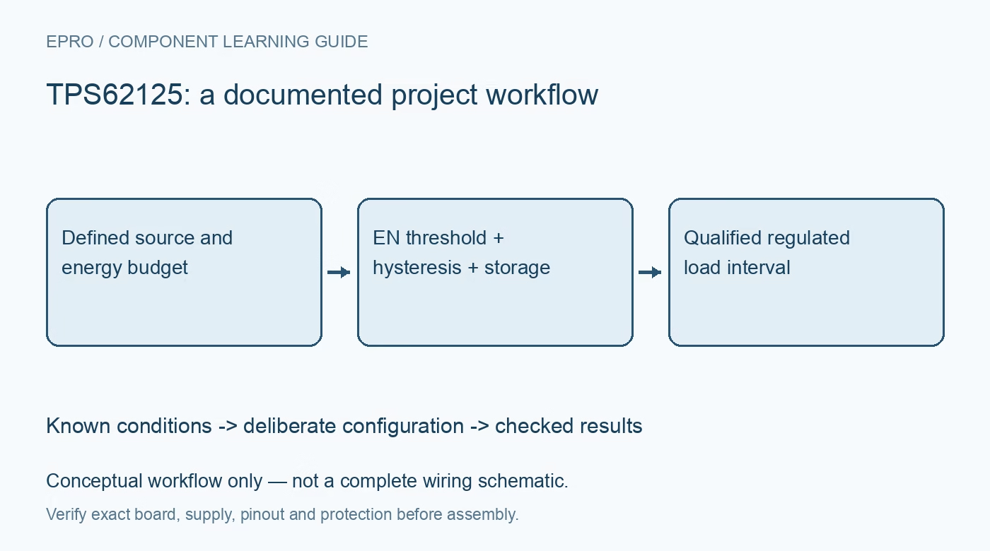
TPS62125 Buck Converter: 7 Checks for Enable Hysteresis and Storage
Design a TPS62125 supply with seven checks for enable thresholds, adjustable hysteresis, storage-capacitor energy, low-input current limits and PG behavior. This is a documentation-based planning guide, not a report of independent hands-on testing.
1. Check current capability across the input range
TPS62125 is a synchronous buck converter intended for a 3 V to 17 V input and an adjustable output within its documented range. The recommended output-current capability is not uniformly 300 mA: the operating table specifies 200 mA below 6 V input and 300 mA from 6 V upward. Use the actual minimum input and thermal conditions when selecting a load. A headline current rating alone is insufficient for a storage-powered system whose input falls during operation. Manufacturer documentation.
2. Distinguish shutdown from supervisor-active waiting
EN controls more than a simple digital switch. A sufficiently low level places the device in shutdown, while the enable-comparator region can leave supervisory circuitry active before regulation begins. The datasheet gives different current consumption for these states. Account for the relevant state in a standby budget, particularly with a high-impedance energy source. A source that can eventually charge a storage capacitor may still be too weak if the waiting circuit continuously consumes most of its available current. Manufacturer documentation.
3. Design rising and falling thresholds separately
The EN comparator uses a nominal rising threshold around 1.2 V and includes hysteresis that can be expanded through EN_hys and its external resistor network. Use the manufacturer equations to calculate both input start and stop voltages, including resistor tolerance and comparator limits. Do not assign an arbitrary GPIO output role to EN_hys. Keep EN terminated and review behavior during a slow ramp, because an unstable threshold arrangement can repeatedly start the converter without ever sustaining the intended load. Manufacturer documentation.
4. Budget usable energy rather than capacitance alone
For capacitor-fed operation, the ideal energy available between two input thresholds is one-half times capacitance times the difference of their squared voltages. Subtract conversion losses and all standing consumption before estimating the useful load interval. Include effective capacitance, leakage and source replenishment under the actual conditions. This is a planning calculation, not a runtime guarantee. A higher start threshold can store more energy, but every voltage must remain within the capacitor, converter and surrounding circuit ratings. Manufacturer documentation.
Newest in the store


5. Match the inductor and output network to the task
Choose the LC components using the documented design procedure, including saturation current, effective ceramic capacitance, minimum timing and light-load operation. Pulse-frequency behavior at low load changes the observed ripple and efficiency compared with heavier PWM operation. Define the measurement bandwidth when evaluating either. Keep the switching loop compact and separate sensitive feedback routing from noisy current paths. A threshold network can be calculated perfectly while a poor power-stage layout still produces unreliable startup or regulation. Manufacturer documentation.
6. Interpret PG and discharge as circuit functions
PG is open drain and needs a suitable pull-up. Its assertion and deassertion thresholds are related to feedback voltage, not a universal statement that the entire downstream system is ready. The device pulls PG low when EN falls below its turn-off threshold or during undervoltage lockout. The documentation also describes using this pin in an output-discharge arrangement. Review the actual connection and pin limits rather than assuming a dedicated unrestricted discharge transistor exists on the output rail. Manufacturer documentation.
7. Validate complete charge-and-run cycles
Test a realistic bounded source, storage element and load rather than only a stiff laboratory input. Capture input voltage, EN, output, PG and load current through charging, startup, operation and shutdown. Confirm that the lower threshold prevents repeated brownout starts and that the source can recharge under the real waiting load. Retain threshold tolerances and temperature conditions with the results. Accept a system on repeatable useful operating intervals, not merely on one successful rise of the output rail. Manufacturer documentation.
Related reading: TPS62150 Buck Converter: 7 Checks for Margining and Tracking.
Catalog note: The exact-part search did not return a matching Epro listing during preparation. Check the current catalog; this guide makes no price, availability or included-accessory claim.