


TPS62150 Buck Converter: 7 Checks for Margining and Tracking

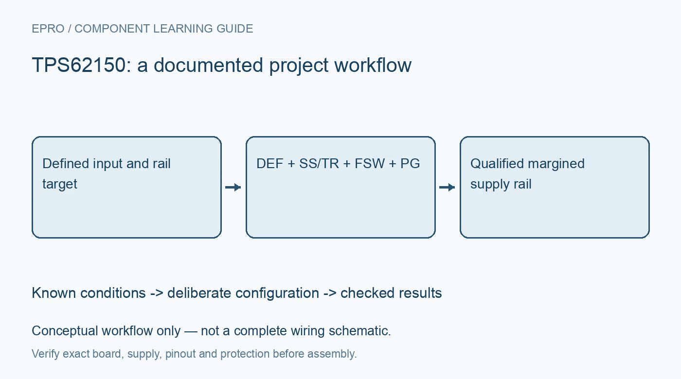
TPS62150 Buck Converter: 7 Checks for Margining and Tracking
Plan a TPS62150 buck rail with seven checks for DEF voltage margining, frequency startup, tracking, LC selection and the TPS62150A power-good difference. This is a documentation-based planning guide, not a report of independent hands-on testing.
1. Distinguish adjustable and suffix variants
The shared datasheet covers the adjustable TPS62150, its A variant and fixed-output relatives. Confirm the complete part number and feedback wiring before selecting a voltage. The family supports a 3 V to 17 V input range and a 1 A class output, subject to operating and thermal conditions. Neither a family headline nor a visually similar board establishes the installed output setting. Record the schematic revision and installed inductor and capacitor values first. Manufacturer documentation.
2. Design the LC network for the chosen mode
Use the manufacturer design guidance for inductance, effective output capacitance, saturation current and ripple. Ceramic capacitance under DC bias can be substantially lower than its marked value. The switching-frequency choice changes the ripple and minimum useful inductance, so it cannot be reviewed separately from the output network. Check the entire input range and load range, including light-load behavior. Layout, exposed-pad connection and the high-current switching loop are part of this review, not finishing details. Manufacturer documentation.
3. Use DEF for the documented five-percent step
DEF low selects the nominal output; DEF high raises it by five percent. This is pin-selectable margining, not an arbitrary programmable voltage command. Calculate the upper rail tolerance after reference, feedback and transient effects, then check every downstream device against that bound. DEF has a lower voltage allowance than the maximum input supply, so do not tie it indiscriminately to VIN. Follow the recommended connection and keep its state defined during startup. Manufacturer documentation.
4. Start with FSW low before selecting lower frequency
FSW low selects the higher switching frequency, typically 2.5 MHz. A high level selects approximately half that frequency for a different efficiency and ripple trade-off. The datasheet requires starting with FSW low to limit inrush; a permanent high strap is not the documented startup arrangement. Review the recommended VOUT or PG based control connection and its voltage limits. Measure startup separately from steady-state frequency behavior rather than assuming both are correct from one waveform. Manufacturer documentation.
Newest in the store


5. Review soft start and tracking as a sequence
An external capacitor on SS/TR controls the startup ramp, while an externally applied tracking voltage can make the output follow a master rail. Confirm the tracking relationship and allowed pin voltage from the application section rather than connecting rails directly by intuition. Consider pre-biased output conditions, source impedance and restart after shutdown. Capture VIN, EN, SS/TR and VOUT together when validating the sequence, with a bounded load and a current-limited input source. Manufacturer documentation.
6. Do not interchange PG shutdown behavior
PG is an open-drain indication requiring a suitable pull-up. For the TPS62150, it is high impedance during shutdown caused by EN, undervoltage lockout or thermal shutdown. The TPS62150A instead drives PG low in those conditions while input power remains present, enabling a documented discharge application. A high pulled-up PG signal on the non-A device therefore does not independently certify a valid disabled rail. Review the logic table for the exact suffix before writing sequencing rules. Manufacturer documentation.
7. Qualify margin changes with the real load
Test nominal and raised-voltage settings at representative input voltages and load steps. Record ripple, startup time, overshoot, settling and PG transitions using suitable probing. A five-percent setpoint change does not guarantee a five-percent instantaneous waveform or safe downstream behavior. Repeat restart and pre-bias cases that can occur in the intended system. Preserve component values, frequency-control timing and suffix information in the acceptance record so a later substitution triggers a meaningful requalification. Manufacturer documentation.
Related reading: TPS62177 Buck Supply: 7 Checks for Sleep Mode and Wake Load.
Catalog note: The exact-part search did not return a matching Epro listing during preparation. Check the current catalog; this guide makes no price, availability or included-accessory claim.