


TPS22916 Load Switch: 7 Checks for Suffixes and Reverse Blocking

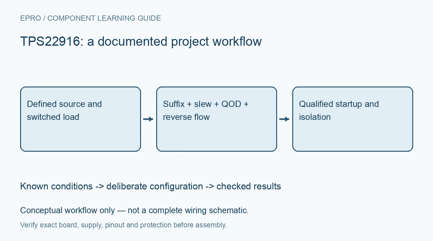
TPS22916 Load Switch: 7 Checks for Suffixes and Reverse Blocking
Select a TPS22916 load-switch variant with seven checks for enable polarity, fixed slew rate, discharge options, reverse blocking and capacitive startup. This is a documentation-based planning guide, not a report of independent hands-on testing.
1. Write down the complete ordering suffix
TPS22916 is a family of small load switches with meaningful suffix differences. B and C options have different fixed turn-on behavior, L options invert enable polarity, and N options omit quick output discharge. A board described only as a TPS22916 switch is not enough information for a safe substitution. Match the full code to the device and function tables, then verify the four-ball package orientation against the actual layout before connecting power. Manufacturer documentation.
2. Separate operating voltage from load capability
The device is intended for a 1 V to 5.5 V input range and a 2 A class load path under its specified conditions. Check on-resistance at the actual voltage, temperature and package implementation, then calculate conduction loss from current squared times resistance. A current headline does not promise acceptable temperature in any enclosure. Account for connector and trace resistance as well, and do not confuse a load switch with a voltage regulator or a complete overcurrent-protection system. Manufacturer documentation.
3. Make the enable polarity explicit
Ordinary variants enable at a high ON level; L variants enable at a low level. Review controller reset, unpowered states and the documented smart bias behavior, not just the steady-state GPIO setting. An active-low substitution can energize a load during boot when the original circuit stayed off. Label the intended physical level in the schematic and firmware interface, and verify the ON threshold against the controlling rail throughout power sequencing rather than relying on a familiar logic label. Manufacturer documentation.
4. Match fixed slew rate to capacitance
The B and C choices provide different internally defined rise-time behavior; this is not the externally programmable CT arrangement of another family member. Estimate startup current using capacitance times voltage slew, then include the load current already flowing during the ramp. Check the source impedance and any upstream current limit. Observe the actual rising output with representative capacitance, because a nominal timing label alone does not describe every voltage, temperature and load combination. Manufacturer documentation.
Newest in the store


5. Choose discharge behavior deliberately
Quick output discharge connects an internal resistance from VOUT to ground when applicable variants are disabled. N variants omit that path. Output fall time consequently depends on both the selected suffix and the external load and capacitance. Review whether another supply can hold VOUT up while the switch is off; an enabled discharge path can then become an unintended load. Do not assume that an off command instantly removes all stored voltage or provides galvanic isolation. Manufacturer documentation.
6. Understand the finite reverse-blocking response
The full-time reverse-current function detects reverse flow when VOUT exceeds VIN and disables the pass path after its specified threshold and response time. It is not an ideal diode with zero transient current. The switch can restart with slew control after the reverse-voltage condition clears. Review the electrical-characteristics conditions for thresholds, delays and leakage, and test only within a protected bounded arrangement. Do not infer unrestricted reverse-voltage tolerance from the feature name. Manufacturer documentation.
7. Capture startup and back-powered states separately
Build an acceptance matrix for normal turn-on, commanded off, input collapse and an externally sustained output. Record the exact suffix, input and output voltages, current direction, load capacitance and ON level. Compare measured behavior with the appropriate timing definitions rather than a single scope cursor reading. If the load can receive power through signal pins, include those paths in the system review; isolating the main supply alone may not actually turn the subsystem off. Manufacturer documentation.
Related reading: TPS22917 Load Switch: 7 Checks for Reverse Blocking and Timing.
Catalog note: The exact-part search did not return a matching Epro listing during preparation. Check the current catalog; this guide makes no price, availability or included-accessory claim.