


TCA9555 GPIO Expander: 7 Checks for Paired Ports and Interrupts

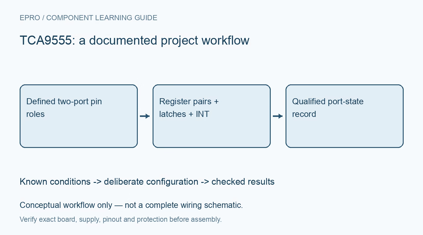
TCA9555 GPIO Expander: 7 Checks for Paired Ports and Interrupts
Configure a TCA9555 GPIO expander with seven checks for paired registers, weak pull-ups, startup latches, interrupt clearing and reliable two-port reads. This is a documentation-based planning guide, not a report of independent hands-on testing.
1. Fix the address and voltage domain
The TCA9555 provides sixteen GPIO pins on a 1.65 V to 5.5 V supply, with three hardware address inputs selecting eight possible bus addresses. Tie A0, A1 and A2 to defined supply or ground levels; do not float them or change them during powered transactions. Check the controller thresholds and bus pull-up voltage independently of the GPIO loads. Use seven-bit addresses consistently in firmware rather than mixing them with shifted address bytes. Manufacturer documentation.
2. Account for the internal weak pull-ups
Unlike some related sixteen-bit expanders, this device includes weak pull-ups on its port pins. They help define otherwise undriven inputs but are not substitutes for a deliberate noise, leakage and switch-interface design. Estimate the current when an input is held low and evaluate external biasing where necessary. The I2C lines and open-drain INT output still need their own suitable pull-ups. A GPIO pull-up does not bias the communication bus or guarantee contact debounce. Manufacturer documentation.
3. Set output latches before enabling drivers
Power-up configures the port pins as inputs. Prepare the desired output-latch values before changing selected configuration bits to outputs, particularly for enables, chip selects and indicator drivers. Treat a direction change as an electrical event, not merely a register edit. Check external load states during reset and controller boot. The configuration map uses one for input and zero for output; retain a reviewed mask so unrelated pins do not accidentally become driven outputs. Manufacturer documentation.
4. Follow the paired-register transaction rule
Input, output, polarity and configuration registers are organized as two-port pairs. Successive transfers alternate within the selected pair rather than behaving like an unrestricted linear register walk. Build an explicit transaction for each function and verify the starting command byte. A long generic burst can repeatedly rewrite the wrong pair. Keep the expected port order beside the driver code, and test asymmetric patterns so swapped port-zero and port-one bytes are immediately visible. Manufacturer documentation.
Newest in the store


5. Distinguish pin readings from latch values
Input registers report the port state, while output-register reads return the stored output data rather than independent confirmation of load voltage. Polarity inversion applies to input-register interpretation, not to the physical output drive. Keep raw pin observations separate from logical application states. When checking an output, compare the commanded latch with an actual input or instrument observation as appropriate; a successful write acknowledgment alone does not prove that a connected actuator reached its intended state. Manufacturer documentation.
6. Clear the interrupt from the responsible port
INT responds to changes on pins configured as inputs. Reading the port that caused the condition resets its interrupt comparison; returning to the original input state can also remove the condition. Reading only the other port is not a universal clear operation. Service both relevant input registers and check INT again, allowing for another edge during the transaction. This is change detection, not a timestamped event FIFO or a guarantee that every short pulse is captured. Manufacturer documentation.
7. Validate two-port behavior under changing inputs
Use a test plan with distinct stable patterns, one-bit changes on each port and changes near a read operation. Record the command byte, both returned bytes, configuration masks and INT level before and after service. Two bytes read sequentially are not a simultaneous sixteen-bit hardware snapshot. If the application needs coherent multi-bit transitions or precise event timing, add suitable external latching or choose a different interface rather than assuming the software read makes them atomic. Manufacturer documentation.
Related reading: TCA9554 GPIO Expander: 7 Checks for Pull-Ups and Interrupts.
Catalog note: The exact-part search did not return a matching Epro listing during preparation. Check the current catalog; this guide makes no price, availability or included-accessory claim.