


TPS62177 Buck Supply: 7 Checks for Sleep Mode and Wake Load

TPS62177 Buck Supply: 7 Checks for Sleep Mode and Wake Load
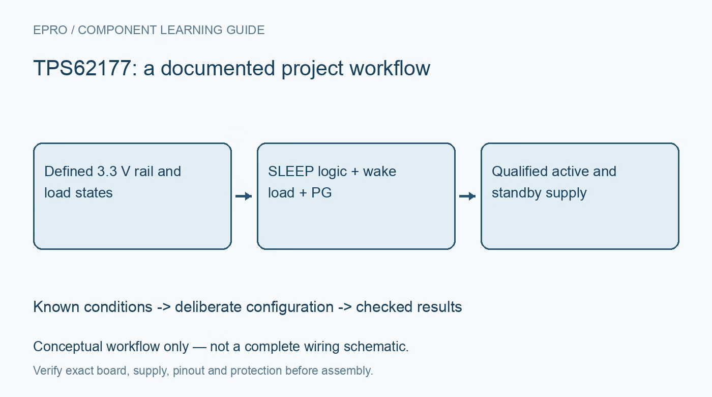
Plan a TPS62177 fixed 3.3 V rail with correct SLEEP polarity, wake-load timing, power-good behavior, component selection and shutdown expectations. This is a documentation-based planning guide, not a report of independent hands-on testing.
1. Identify the fixed-output device and its source range
TPS62177 is the fixed 3.3 V member of the TPS6217x step-down family, while TPS62175 is adjustable. Verify the actual device and sensing connections rather than copying an adjustable-family divider. The documented input range is 4.75 V to 28 V, with up to 500 mA output under appropriate design conditions. This is not a boost converter. Include source droop and wiring resistance when establishing the minimum input available to the assembled regulator under its largest load. Manufacturer documentation.
2. Separate automatic power saving from host-controlled sleep
Light-load power-save behavior and the dedicated sleep operating mode are different features. Sleep reduces typical quiescent consumption further but also limits dynamic response and load capability. It is intended for a deliberately low-power application state, not as the default mode for an arbitrary 500 mA load. Define expected active, standby and wakeup loads before choosing the control policy. The host and regulator should agree about when the rail is allowed to deliver only the documented sleep-mode performance. Manufacturer documentation.
3. Use the correct SLEEP polarity and pin voltage
The documented scheme uses SLEEP low for sleep operation and high to leave it. The manufacturer advises connecting SLEEP to VOUT, not a higher VIN, when sleep is not wanted because the pin has its own voltage limit. An internal pulldown supports a low state when a host pin floats, but host leakage can affect a high-to-floating transition. Check the real GPIO state during deep sleep and reset rather than assuming its software value remains actively driven. Manufacturer documentation.
4. Exit sleep before demanding a sustained active load
The device can temporarily supply wakeup current, but continuous excessive sleep-mode load can pull the rail down. The datasheet describes an automatic return to normal operation when the resulting power-good condition demands it, while explicitly discouraging use of this as the normal operating policy. Schedule the SLEEP transition before enabling radio bursts, sensors or processors that need substantial current. Measure rail behavior during the actual wake sequence; a successful standby reading does not qualify the active-load transition. Manufacturer documentation.
Newest in the store


5. Interpret PG using this family rather than another buck
PG is open drain and needs an appropriate pull-up to produce a logic-high indication. Unlike some nearby converter families, this datasheet states that PG is held low when disabled by EN, undervoltage lockout or thermal shutdown. Do not import a high-impedance shutdown rule from TPS62160 without checking the difference. Validate pull-up voltage and the host reading throughout power sequencing. PG is a regulation indicator, not a measurement of load current or a guarantee that every downstream device has completed its own startup. Manufacturer documentation.
6. Select the power network and discharge behavior together
Choose the inductor and input/output capacitance using the manufacturer stability and component guidance, including effective ceramic capacitance under bias. Check inductor saturation, source ripple, thermal layout and the exposed pad. Shutdown includes active output discharge, which differs from entering sleep while maintaining a regulated standby rail. Define which transition the load actually needs. Do not equate output discharge with unrestricted reverse-current protection or assume a fixed reset interval without checking load capacitance and the implemented circuit. Manufacturer documentation.
7. Validate sleep, startup and repeated wake cycles
Bring up with a current-limited source and bounded noncritical load, then test startup before sleep, standby current, a commanded wake and the largest approved load step. Observe VIN, VOUT, SLEEP and PG together where possible. Record external components, source settings, load profile and host GPIO behavior during reset. Stop if the rail repeatedly collapses or components overheat. This manufacturer-documentation guide provides a design review path, not measured battery life, wakeup timing or continuous-load validation for an untested board. Manufacturer documentation.
Related reading: TPS62160 Buck Converter: 7 Checks for Power-Good Interpretation.
Catalog note: The exact-part search did not return a matching Epro listing during preparation. Check the current catalog; this guide makes no price, availability or included-accessory claim.