


TMP103 Sensor Network: 7 Checks for Multiple-Device Reads

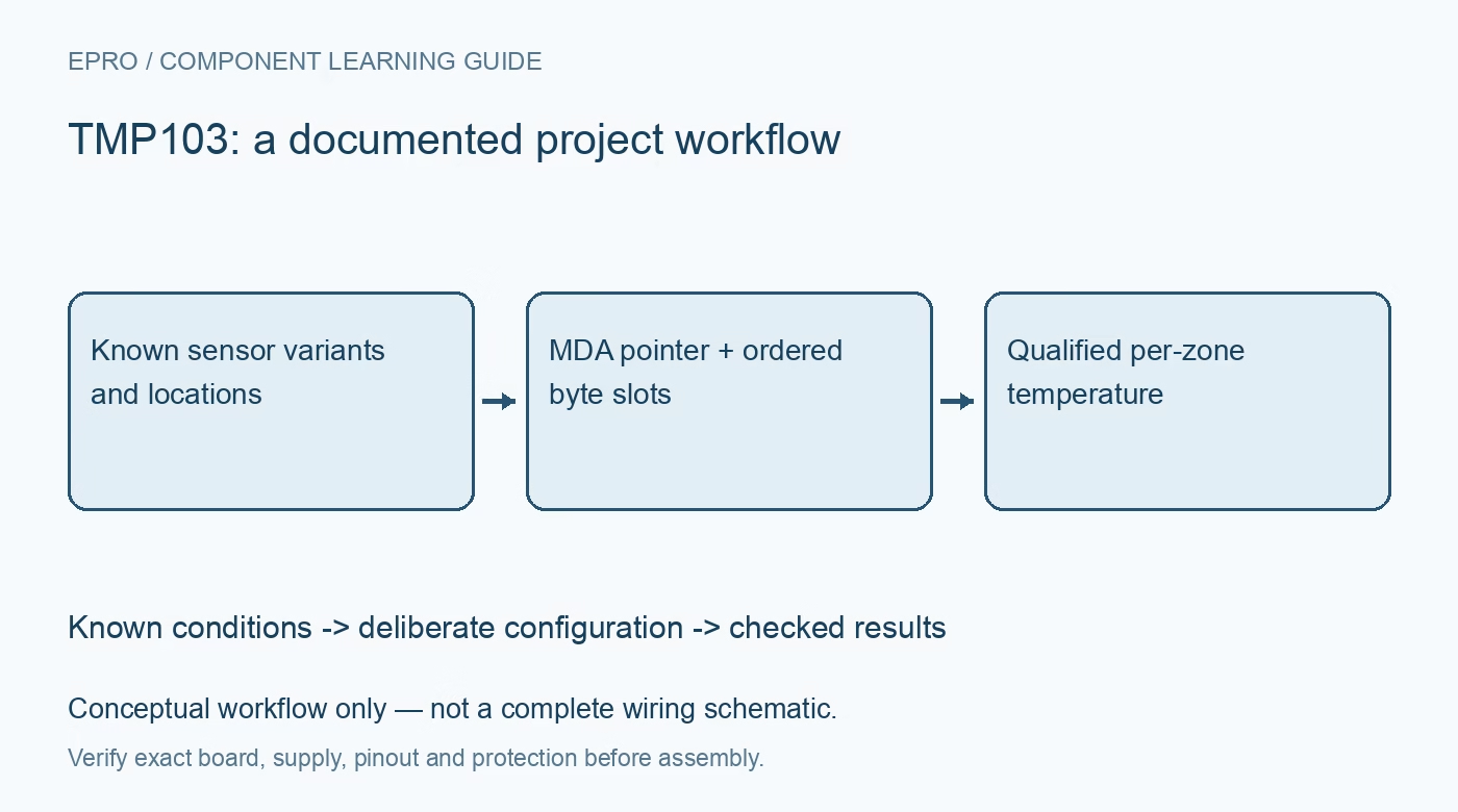
TMP103 Sensor Network: 7 Checks for Multiple-Device Reads
Plan TMP103 temperature networks with fixed-address variants, signed eight-bit values, multiple-device read ordering and dummy slots for missing variants. This is a documentation-based planning guide, not a report of independent hands-on testing.
1. Map fixed-address variants to physical locations
TMP103 is a four-ball temperature sensor with fixed-address product variants and an eight-bit output. Choose distinct supported variants for sensors sharing a bus and record which thermal zone each variant represents. There is no extra address-strapping pin hidden in the tiny package. Verify footprint orientation and the documented 1.4 V to 3.6 V supply range. The ability to read several sensors in one transaction does not identify their physical locations unless the hardware and firmware share the same mapping. Manufacturer documentation.
2. Decode one signed byte at one degree per count
The temperature register contains an eight-bit twos-complement value with a 1 degree Celsius step. It is not the left-justified twelve-bit result of a different temperature family. For example, a negative code must be sign-extended from eight bits rather than interpreted as a large unsigned temperature. Test decoding with known positive, zero and negative vectors. Code spacing and accuracy are different: a typical accuracy headline is not a maximum error guarantee over every temperature and mounting condition. Manufacturer documentation.
3. Establish individual access before enabling global operations
First communicate with each intended device through its ordinary address, verifying pointer behavior and a plausible temperature response. This provides a baseline for wiring and location checks before Multiple Device Access is used. Confirm bus pull-ups, capacitance and host timing with all sensors connected. MDA is a special protocol feature, not a general permission to let arbitrary identical-address I2C targets drive the bus together. Other devices on the same bus must also be reviewed for compatibility with the chosen transactions. Manufacturer documentation.
4. Set the shared pointer deliberately for an MDA transaction
The manufacturer defines MDA write and read operations separately. Before an MDA read, a write transaction sets the desired register pointer, after which the read returns the ordered device data. A global write can deliberately place the same register value in all participating sensors, which is useful but broader than an individual update. Keep global configuration changes explicit in the driver. Do not assume the pointer already selects temperature merely because a previous individual read did so. Manufacturer documentation.
Newest in the store


5. Preserve missing-variant slots instead of compressing the map
MDA read ordering follows device variants, not the order in which firmware discovered sensors. The datasheet requires dummy bytes for missing variants in an incomplete sequence. For example, with variants A, B and D, the host must clock through four slots rather than collecting three bytes and labeling the third as D. Follow the documented acknowledge behavior for all required slots. Store slot validity separately so an absent device cannot shift every later sensor into the wrong thermal-zone record. Manufacturer documentation.
6. Track conversion timing independently of bus-read speed
The temperature register holds the most recent completed conversion and initially reads zero until the first conversion completes after reset. Repeated or global reads do not force simultaneous new conversions. Configure the conversion policy and allow the documented timing before qualifying a sample. If coherent timing across zones is important, establish how conversions are initiated and how much sample-age difference is acceptable. A compact global transaction reduces communication overhead, but it does not by itself prove all sensing elements measured at the same instant. Manufacturer documentation.
7. Validate the network with missing devices and recovery tests
Test individual reads, a complete MDA sequence and a deliberately absent variant using noncritical monitoring hardware. Confirm byte count, ordering, acknowledgements and mapping after bus errors or a power cycle. Compare stabilized temperatures against a suitable reference while considering local board heating and the chip thermal path. Record variant-to-location mapping and raw returned bytes in diagnostic logs. This documentation-based guide makes no independent multi-zone accuracy, calibration or safety-critical thermal-protection claim for an assembled system. Manufacturer documentation.
Related reading: TMP110 I2C Sensor: 7 Checks for Variant Pins and Data Format.
Catalog note: The exact-part search did not return a matching Epro listing during preparation. Check the current catalog; this guide makes no price, availability or included-accessory claim.