


DRV8835 Dual Driver: 7 Checks for Modes and Logic-Supply Sleep

DRV8835 Dual Driver: 7 Checks for Modes and Logic-Supply Sleep
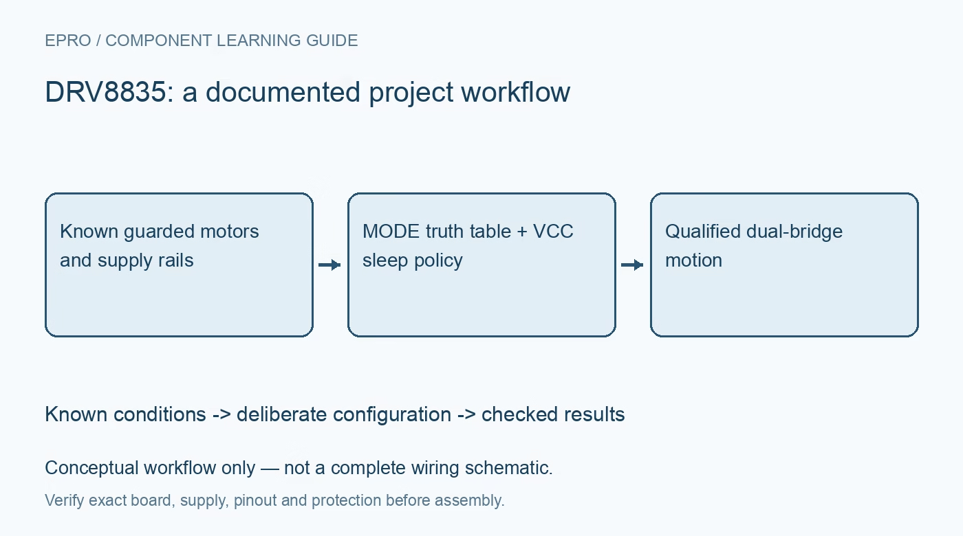
Plan DRV8835 dual-motor control with the correct interface mode, braking truth table, separate supplies and actual VCC-based sleep behavior. This is a documentation-based planning guide, not a report of independent hands-on testing.
1. Identify two full bridges and their shared constraints
DRV8835 contains two full H-bridges for two DC motors or one supported stepper arrangement. It is not the two-half-bridge architecture of DRV8839 despite the nearby family names. Check package, pinout, common supply paths and thermal copper before designing the controller interface. The 1.5 A per-bridge headline is not a guarantee of sustained current for two simultaneously loaded motors on any board. Estimate startup, stall and operating currents and provide guarded mechanics and a physical motor-power removal method. Manufacturer documentation.
2. Separate VM capability from the VCC requirement
The documented motor supply range extends from 0 V to 11 V, while the logic supply operates from 2 V to 7 V. These pins have different roles and limits. Check controller logic levels and sequencing rather than assuming the motor rail can power VCC directly at every allowed VM value. Include motor-start droop, local bypassing and wiring transients. A zero motor supply can be a legal condition, but it does not turn the device into a logic-powered motor-energy source. Manufacturer documentation.
3. Make the MODE setting part of the firmware contract
MODE low, including the documented unconnected default, selects IN/IN control. MODE high selects PHASE/ENABLE. The same physical control pins therefore have different meanings depending on the mode. Define the actual board connection and keep firmware configuration consistent with it. Do not transplant a generic direction-and-enable abstraction without checking the truth table. If MODE could change during host reset, review the resulting output states before enabling either bridge; a transient pin interpretation can be a real motion command. Manufacturer documentation.
4. Distinguish braking from coasting in each interface
In IN/IN mode, both control inputs low produce high-impedance coast, while both high produce low-side braking; mixed states select direction. In PHASE/ENABLE mode, enable low produces braking, not coast. That distinction is essential when a program calls a function named disable or stop. Check both motor-terminal voltages and guarded mechanical behavior at conservative settings. Braking can reduce stopping time, but neither a software state nor a driver truth table guarantees an immediate, safety-rated mechanical stop. Manufacturer documentation.
Newest in the store


5. Use the actual logic-supply sleep mechanism
The datasheet sleep section specifies entering low-power sleep when VCC reaches 0 V, with inputs kept low for minimum consumption. Do not invent a dedicated nSLEEP package pin from a related driver or confuse a zero-duty enable command with the documented sleep condition. Design VCC control and host pin behavior deliberately, avoiding unintended powering through signal connections. Consult package pin functions and timing when restoring VCC. A complete low-power policy covers both the logic supply and all externally driven inputs. Manufacturer documentation.
6. Treat bridge paralleling and protection as engineered features
The manufacturer documents a particular parallel-bridge arrangement for higher drive capability. Follow its matching input and output connections exactly; do not short independently commanded outputs together. Current sharing, package dissipation and board copper still determine suitability. Internal overcurrent, undervoltage and thermal protections are fault responses, not precision programmable motor-current regulation. Automatic recovery can restore drive after a transient, so application-level controls must prevent an unexpected restart. Investigate repeated protection cycling rather than counting it as normal operating behavior. Manufacturer documentation.
7. Verify mode, stop and reset behavior with bounded motion
Start with a current-limited source and safely mounted lightly loaded motors. Check direction and both stop definitions in the chosen interface, then exercise host reset and the documented VCC sleep transition. Test both bridges together only inside the established electrical and thermal envelope. Save wiring, MODE level, duty cycle, motor identity and accepted load profile. Disconnect power before changing motor or parallel connections. This manufacturer-based planning guide claims no measured continuous-current rating, calibrated torque or functional-safety certification. Manufacturer documentation.
Related reading: DRV8839 Motor Driver: 7 Checks for Independent Half-Bridge Control.
Catalog note: The exact-part search did not return a matching Epro listing during preparation. Check the current catalog; this guide makes no price, availability or included-accessory claim.