


DRV8839 Motor Driver: 7 Checks for Independent Half-Bridge Control

DRV8839 Motor Driver: 7 Checks for Independent Half-Bridge Control
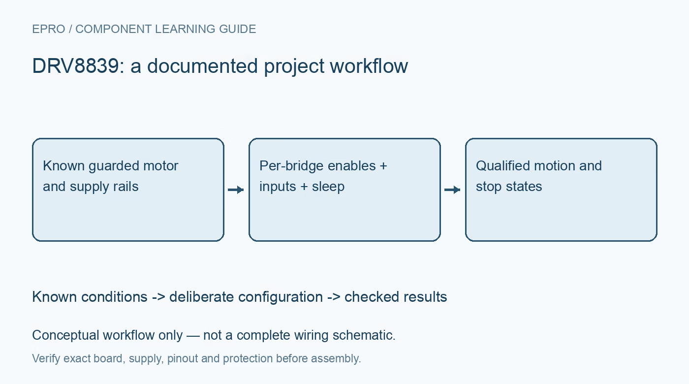
Plan DRV8839 drive control with separate logic and motor supplies, per-output enables, braking states, sleep timing and protection without fault telemetry. This is a documentation-based planning guide, not a report of independent hands-on testing.
1. Identify two half bridges rather than two reversible motors
DRV8839 contains two independently controlled half bridges. Together they can form one full bridge for a bidirectional DC motor or drive other supported load arrangements. Two motors can be connected in the documented unidirectional arrangement, but the part does not contain two complete bidirectional motor bridges. Draw the actual current paths before choosing firmware commands. Confirm the compact WSON package, exposed-pad connection and thermal layout; a maximum-current headline is not a universal continuous rating for a finished board. Manufacturer documentation.
2. Treat motor power and logic power as separate domains
The documented motor supply range extends from 0 V to 11 V, while the device logic supply has its own 1.8 V to 7 V range. The ability for VM to be zero does not mean the driver operates without a valid logic supply. Check input logic thresholds and supply sequencing with the actual controller. Include motor-start droop, wiring inductance and decoupling in the plan. Do not apply a higher motor voltage merely because a different nearby driver family allows it. Manufacturer documentation.
3. Define each output using its enable and input
For an awake device, ENx low makes that half-bridge output high impedance. With ENx high, INx low drives the output low and INx high drives it high. This is not the single PH/EN interface of DRV8838. Preserve separate control of both channels in the firmware abstraction, and define reset defaults for every line. A high-impedance output is not a measured zero-voltage node; the load and external circuitry can determine its voltage when the switches are disabled. Manufacturer documentation.
4. Map motor braking and coasting to the actual bridge states
With both half bridges enabled, opposite input states drive opposite directions. Equal input states drive both motor terminals to the same rail, producing the documented braking condition. Disabling a half bridge opens the relevant drive path and provides the documented coast behavior for the motor connection. Verify the electrical state rather than relying on a function named stop. The mechanical stopping time depends on motor, inertia and load, so software disable must not be presented as an immediate safety stop. Manufacturer documentation.
Newest in the store


5. Include sleep and wakeup in command sequencing
nSLEEP low disables the outputs and internal circuitry under the documented sleep behavior. Keep this signal at a deterministic level during controller startup and allow the specified wakeup timing before commanding motion. Distinguish disabling one output from putting the entire device to sleep. If the motor supply remains present while the host resets, external bias and the logic supply sequence must prevent unexpected drive. Disconnect motor power before changing connections, and provide a physical power-removal method during testing. Manufacturer documentation.
6. Do not confuse internal protection with telemetry or regulation
The device provides undervoltage, overcurrent and overtemperature protection with documented automatic recovery behavior. The protection table lists no external error report for these events; do not invent an nFAULT pin or a readable status register. Protective current limiting is not a user-programmable precision motor-current controller. Repeated shutdown and recovery can cause intermittent motion or heating, so diagnose source droop, overload and thermal design separately. A system requiring explicit fault reporting needs suitable external observations or a different supported architecture. Manufacturer documentation.
7. Test only bounded motion with guarded hardware
Start with a current-limited source and a safely mounted, lightly loaded motor. Verify both directions, each enable, both braking states and sleep recovery at conservative settings. Measure supply and temperature without creating deliberate output shorts or destructive stalls. Record motor identity, load, duty cycle, supply values and controller reset behavior. Check that automatic protection recovery cannot restart a hazardous action. This documentation-based guide claims no measured continuous-current capability, calibrated torque control or functional-safety approval for an assembled mechanism. Manufacturer documentation.
Related reading: DRV8838 Motor Driver: 7 Checks Before Treating Disable as Coast.
Catalog note: The exact-part search did not return a matching Epro listing during preparation. Check the current catalog; this guide makes no price, availability or included-accessory claim.