


DAC8551 Voltage DAC: 7 Checks for Feedback and Serial Updates

DAC8551 Voltage DAC: 7 Checks for Feedback and Serial Updates
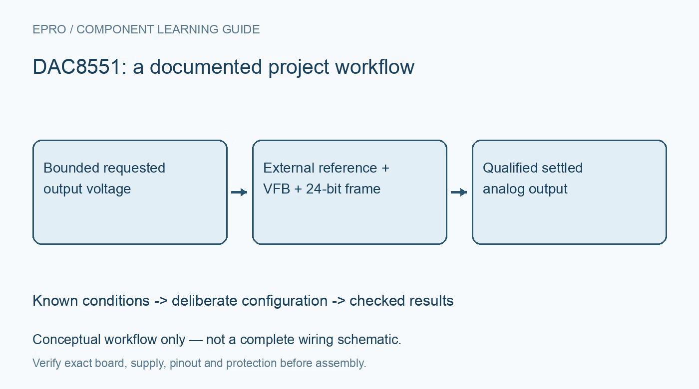
Plan DAC8551 voltage generation with external reference, VFB wiring, straight-binary coding, complete twenty-four-clock writes and explicit power-down behavior. This is a documentation-based planning guide, not a report of independent hands-on testing.
1. Define the external reference and output load
DAC8551 is a sixteen-bit voltage-output DAC that requires an external reference to set its span. Verify supply, reference and output limits separately before selecting a requested voltage. The buffered output is not a motor supply or a high-current programmable source. Identify the load resistance, capacitance and any externally driven voltage. A reference connected to a noisy supply transfers that noise into the output scale even when the numerical code remains constant, so treat reference quality as an analog design requirement. Manufacturer documentation.
2. Connect VFB as part of the amplifier feedback path
The output amplifier inverting input is exposed at VFB. In the ordinary documented arrangement, feedback must return from the intended output point; leaving VFB floating is not a valid unity-gain configuration. Remote sensing or additional conditioning requires a deliberate stable loop, not an arbitrary long wire added after assembly. Review load-point feedback, capacitance and grounding together. Check this connection with power removed before interpreting an unexpected rail-level output as a digital communication fault or a bad DAC. Manufacturer documentation.
3. Use straight-binary scaling and preserve endpoint headroom
The ideal relation is VOUT = VREF times code divided by 65536, for codes zero through 65535 in the standard arrangement. Full-scale code is therefore one ideal step below the reference, not exactly the reference voltage. DAC8551 uses straight binary, unlike a twos-complement counterpart. Include offset, gain error, linearity and output-swing limitations in the practical budget. Monotonic sixteen-bit coding does not establish sixteen-bit absolute voltage accuracy, especially near output limits or with an uncertain reference. Manufacturer documentation.
4. Send the complete twenty-four-bit control and data frame
A write contains six unused leading bits, two power-down control bits and sixteen data bits. Data are clocked on the documented falling SCLK edges, with the requested function executed on the twenty-fourth falling edge. A generic sixteen-bit SPI word cannot represent the complete command. Hold SYNC appropriately and provide its required high interval before starting another write. Verify the captured bit order and control fields with known patterns rather than accepting any output change as evidence of correct alignment. Manufacturer documentation.
Newest in the store


5. Distinguish an interrupted write from a valid update
Raising SYNC before the twenty-fourth falling edge interrupts the sequence, resets the serial shift operation and leaves the DAC register and operating mode unchanged. The next output measurement can therefore look stable while the intended new command was never accepted. Track transfer errors separately from analog settling. When a host reset or bus conflict interrupts an update, resume with a complete deliberate frame. Do not append remaining bits to an abandoned transaction and assume the DAC will reconstruct the original word. Manufacturer documentation.
6. Specify the output state during reset and power-down
Power-on reset initializes the output to zero under the documented behavior until a valid write occurs. Serial power-down selections provide different output conditions: approximately 1 kOhm to ground, approximately 100 kOhm to ground or high impedance. These are not interchangeable definitions of zero volts, particularly with an externally biased load. The stored DAC code is retained during power-down, and wakeup takes time. Define which state is safe for the application and measure the actual node after entering it. Manufacturer documentation.
7. Validate unloaded levels before testing the real load
Begin with known codes at zero, midscale and near full scale using a suitable voltage instrument and a verified reference. Allow documented settling time after a complete write or power-down exit. Repeat with the approved load while checking output error, overshoot and amplifier headroom. Save supply, reference, feedback connection, frame bytes and load conditions. This manufacturer-based guide provides a review workflow, not measured accuracy or a guarantee that a code-to-voltage calculation alone validates the finished board. Manufacturer documentation.
Related reading: DAC60501 DAC: 7 Checks for a Predictable Voltage Output.
Catalog note: The exact-part search did not return a matching Epro listing during preparation. Check the current catalog; this guide makes no price, availability or included-accessory claim.