


PCA9515A I2C Repeater: 7 Checks for Pull-Ups and Clock Stretching

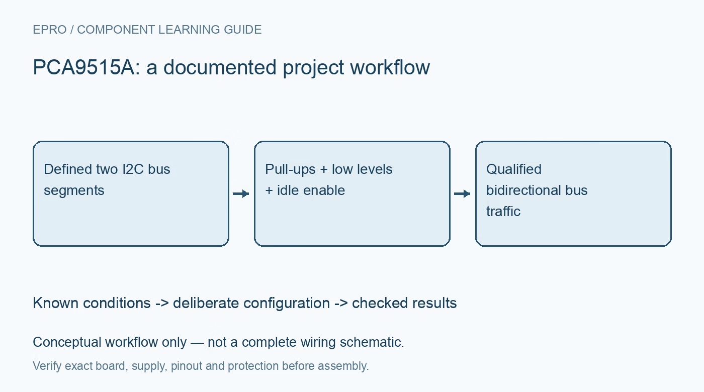
PCA9515A I2C Repeater: 7 Checks for Pull-Ups and Clock Stretching
PCA9515A checks for buffer low levels, pull-ups, enable timing, cascade restrictions and the clock-stretch accelerator warning. This is a documentation-based planning guide, not a report of independent hands-on testing.
1. Treat the part as a repeater rather than an isolator
The PCA9515A buffers SDA and SCL bidirectionally between two I2C bus segments. It does not create galvanic isolation, assign addresses or translate commands between unrelated protocols. Its supply operates from 2.3 V to 3.6 V, while the documented bus and enable input tolerance permits higher logic levels within specified limits. Draw both segments, their pull-up rails and their common reference explicitly. A two-sided symbol alone does not establish safe separation between different electrical ground systems. Manufacturer documentation.
2. Design pull-ups independently on both sides
Each bus segment requires its own suitable pull-ups. The repeater separates capacitive loading, but rise time, sink current and receiver voltage requirements still have to be checked for each side. Mixed-voltage buses are possible within the documented limits; do not infer that any arbitrary pair of rails works. Calculate the resistor range from bus capacitance and low-level current capability, then inspect waveforms at both ends. A universal resistor value copied from another board is not a substitute for this calculation. Manufacturer documentation.
3. Account for the deliberate low-level offset
The buffer uses a static low-level offset, with an output low of roughly 0.5 V under the relevant conditions. Its input recognition must distinguish an externally driven low from that internally driven level; the documented separation is approximately 70 mV below the output low. Verify actual downstream input-low limits and measurement conditions. A buffered low should not automatically be classified as a wiring fault because it is higher than a direct transistor pull-down, nor assumed valid for every possible receiver. Manufacturer documentation.
4. Do not place repeaters in an unrestricted series chain
Two or more PCA9515A devices cannot simply be cascaded in series. The buffered low from one device does not satisfy the recognition requirements of the next in the way an ordinary wire would. If the topology requires multiple buffering stages, choose a manufacturer-supported architecture and compatible parts rather than extending the drawing by repetition. Check existing onboard buffers in modules as well as newly added components. A hidden repeater on a breakout can create an unsupported series path unintentionally. Manufacturer documentation.
Newest in the store


5. Change enable only while the bus is idle
EN is active high and includes an internal pull-up. Switching it changes whether traffic propagates between segments, so follow the requirement to change enable only when both sides are idle. It is not an addressed channel-selection register or a protocol-aware traffic scheduler. The power-off high-impedance behavior of the bus pins also does not guarantee isolation of every external board connection. Verify startup, disabled and re-enabled states using actual SDA and SCL levels rather than relying solely on firmware intent. Manufacturer documentation.
6. Respect the clock-stretching accelerator warning
The manufacturer explicitly warns against using the PCA9515A with rise-time accelerators because clock-stretching behavior can be corrupted. Overshoot above approximately 500 mV during the relevant stretch condition can propagate an incorrect logic state. Treat this as an architectural compatibility constraint, not a suggestion to fix every case with a different resistor. Inventory accelerators and active pull-ups already present in connected modules. Validate legitimate target clock stretching on both segments before considering the interface ready for normal operation. Manufacturer documentation.
7. Validate rate and recovery without assuming conversion
The device supports the documented Fast-mode bus operation up to 400 kHz; it does not convert a 400 kHz transaction into a slower transaction for a 100 kHz-only target. Such a segment must not receive unsupported traffic. Record pull-up values, rail voltages, low levels, rise times, stretch behavior and idle-enable sequencing. Exercise target reset and host timeout recovery with noncritical peripherals. A successful address scan proves neither timing compliance nor correct behavior during a stretched clock or interrupted transfer. Manufacturer documentation.
Related reading: ISO1540 I2C Isolator: 7 Checks for a Complete Bus Barrier.
Catalog note: The exact-part search did not return a matching Epro listing during preparation. Check the current catalog; this guide makes no price, availability or included-accessory claim.