


INA381 Current Monitor: 7 Checks for Comparator Routing and Alert Timing

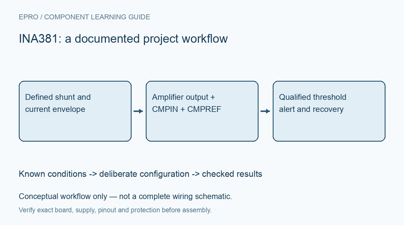
INA381 Current Monitor: 7 Checks for Comparator Routing and Alert Timing
INA381 checks for the separate CMPIN path, externally driven threshold, gain selection, latched alerts and end-to-end timing. This is a documentation-based planning guide, not a report of independent hands-on testing.
1. Define the monitored bus independently from supply
The INA381 combines a current-sense amplifier and comparator, with a recommended supply of 2.7 V to 5.5 V and input common-mode range from minus 0.2 V to 26 V. These are different operating limits, not interchangeable supply options. Select the exact gain version: 20, 50, 100 or 200. Define shunt resistance, current direction, temperature and normal transients before choosing a trip point. Initial validation should use a protected low-voltage dummy-load fixture, not the highest bus voltage mentioned in the datasheet. Manufacturer documentation.
2. Connect the comparator signal path deliberately
CMPIN is a separate comparator input rather than an assumption hidden inside the amplifier block. For a basic overcurrent monitor, the manufacturer directs connecting VOUT to CMPIN when additional hysteresis is not required. If an external network is inserted, it changes what the comparator sees and can add loading, delay or hysteresis. Verify the actual package pins and complete signal route. A correct amplifier output on an oscilloscope does not prove the alert comparator is receiving that voltage. Manufacturer documentation.
3. Set CMPREF with a real voltage source model
CMPREF establishes the comparator threshold through an external reference or divider. It is not an internal eighty-microamp limit-setting pin that accepts a copied resistor-to-ground formula from another monitor. With VOUT routed directly to CMPIN, the nominal positive-current trip follows threshold voltage divided by amplifier gain and shunt resistance. Include source tolerance, reference noise, amplifier offset and gain error. Check comparator input limits and output headroom so the desired threshold lies inside a reachable, valid signal range. Manufacturer documentation.
4. Separate comparator delay from the full measurement path
The fast comparator propagation figure does not include every amplifier settling and system-response contribution. Overdrive, input-step size, gain and output slew affect when a shunt event produces an alert. Host interrupt handling and any external actuator add further time. Define the measurement point for each timing claim instead of presenting a few hundred nanoseconds as a guaranteed complete protection response. Test bounded current steps and capture shunt stimulus, VOUT, CMPIN and ALERT together with suitable instrumentation. Manufacturer documentation.
Newest in the store


5. Account for hysteresis in both trip directions
The comparator has documented hysteresis, so the alert release condition differs from the initial crossing condition. Additional hysteresis circuitry changes this relationship and must be reviewed using the application equations and loading limits. Measure both increasing-current and decreasing-current behavior rather than reporting one threshold from a single sweep. Avoid treating noise-induced toggles as random firmware failures before checking reference stability and the actual comparator input. A useful trip specification includes its release band and tolerances as well as its nominal current. Manufacturer documentation.
6. Select transparent or latched recovery explicitly
RESET low selects transparent mode, while RESET high selects latching. A latched active-low alert remains asserted after the event ends. Clearing requires a low RESET pulse of at least 100 ns when the input has returned below the applicable threshold; return RESET high to rearm latching. ALERT is open-drain and needs a compatible pull-up. Do not interpret a persistent stored alert as continuing measured current, and do not clear a continuing hardware fault merely to make a status display appear healthy. Manufacturer documentation.
7. Qualify indication separately from power interruption
Record exact gain, shunt, threshold source, comparator routing, supply, hysteresis, latch state and measured timing. Verify startup, bounded overload, release and clear-and-rearm behavior. The INA381 reports a condition; it does not itself provide a series disconnect or replace an independently reviewed protection mechanism. Any switch, fuse or shutdown actuator needs a separate response and fault analysis. The acceptance result should establish what voltage caused the alert, how long the complete observed path took and what recovery action was actually verified. Manufacturer documentation.
Related reading: INA302 Current Monitor: 7 Checks for Warning and Critical Alerts.
Catalog note: The exact-part search did not return a matching Epro listing during preparation. Check the current catalog; this guide makes no price, availability or included-accessory claim.