


UCC27519 Gate Driver: 7 Checks for CMOS Input Thresholds and Enable

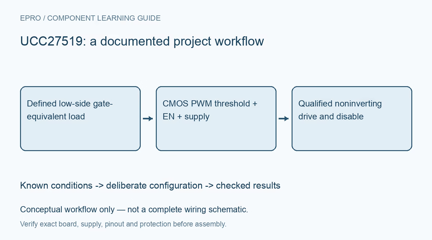
UCC27519 Gate Driver: 7 Checks for CMOS Input Thresholds and Enable
UCC27519 checks for supply-dependent PWM thresholds, a different enable threshold, noninverting logic and protected gate-load tests. This is a documentation-based planning guide, not a report of independent hands-on testing.
1. Confirm the noninverting single-input variant
The UCC27519 is a single-channel noninverting low-side gate driver. The related UCC27518 is inverting, so the shared datasheet does not make their input polarity interchangeable. There is one gate-drive output and a separate enable input, not two independently commanded outputs. Confirm the full part number and pinout before planning connections. Keep the power stage disconnected for initial checks and use a benign capacitive gate-equivalent load with a current-limited low-voltage supply rather than an energized switching converter. Manufacturer documentation.
2. Calculate PWM compatibility from driver supply
The main IN threshold uses CMOS-style, supply-dependent levels. A microcontroller signal that works with a low driver supply may not reach a valid high when the driver is supplied at 12 V. Do not transfer a fixed TTL-threshold assumption from another UCC2751x member. Compare guaranteed host output levels with the electrical table at the actual driver supply, including noise margin and temperature. The ability to tolerate an input voltage is different from the ability to recognize it as logic high. Manufacturer documentation.
3. Review enable separately from the PWM input
EN is active high, but unlike the main IN pin, its threshold is based on compatible low-voltage logic and does not track the driver supply in the same way. Thus a controller may successfully enable the part while failing to drive a valid PWM high. The internal EN pull-up allows an unconnected enable for standard operation, but that default is enabled, not a deliberate startup inhibit. If the application needs controlled blanking, provide a reviewed physical enable state through reset and supply transitions. Manufacturer documentation.
4. Keep gate-voltage limits separate from UVLO
The recommended supply range is 4.5 V to 18 V. Undervoltage lockout holds the output low until the supply is sufficient, but does not establish that every transistor gate is safe at the selected drive voltage. Check gate-source limits, ringing and the intended on-state voltage together. Output amplitude follows the driver supply, not the controller logic rail. Use appropriate low-voltage measurement references and never attach a grounded probe clip to an unknown switching potential or energized high-voltage power stage. Manufacturer documentation.
Newest in the store


5. Treat four-amp drive as a pulse capability
The specified 4 A source and 4 A sink capabilities describe peak gate-drive behavior under stated conditions, not continuous output current or permissible switched load current. Average gate-drive demand depends on charge, voltage and frequency, with package and resistor dissipation considered separately. A large gate-equivalent capacitor can increase heating even if the output reaches the correct amplitude. Select series resistance and edge speed using a reviewed load model rather than maximizing peak current merely because it appears in the feature list. Manufacturer documentation.
6. Preserve bypass and return-path integrity
The manufacturer recommends local ceramic bypassing and additional nearby bulk capacitance to support high-current pulses. Keep the gate-drive loop and ground return compact so output current does not corrupt the input reference. Typical propagation, rise and fall figures depend on supply and test load and are not universal end-to-end timing guarantees. Review any input filter against the supply-dependent thresholds and desired delay. A smooth signal observed at the controller does not establish a clean or correctly timed signal at the driver pins. Manufacturer documentation.
7. Verify threshold and disable behavior before power switching
With only the protected gate-equivalent load connected, record supply, IN amplitude, EN state, output polarity, edge shape and temperature. Exercise enable transitions and supply ramps, including a valid-enable but insufficient-PWM-level case using safe test levels. This qualifies the bounded driver fixture only. A power-stage connection still requires a separate topology, protection and instrumentation review. The acceptance report should distinguish logic recognition, output disable and gate-drive capability instead of treating one attractive waveform as proof of a complete safe converter. Manufacturer documentation.
Related reading: UCC27517 Gate Driver: 7 Checks for Input Interlocks and Gate Loading.
Catalog note: The exact-part search did not return a matching Epro listing during preparation. Check the current catalog; this guide makes no price, availability or included-accessory claim.