


TCA9517 I2C Repeater: 7 Checks for Buffered Lows and Bus Topology

TCA9517 I2C Repeater: 7 Checks for Buffered Lows and Bus Topology
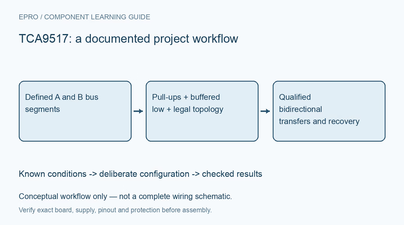
TCA9517 checks for asymmetric low levels, pull-ups on both sides, forbidden B-to-B connections, enable thresholds and stretching. This is a documentation-based planning guide, not a report of independent hands-on testing.
1. Keep the two supply domains and their limits explicit
The TCA9517 supports an A-side supply from 0.9 V to 5.5 V and a B-side supply from 2.7 V to 5.5 V. It buffers SDA and SCL bidirectionally while separating bus loading and translating voltage levels. It is not a galvanic isolator, addressed mux or protocol converter. Identify the exact variant rather than substituting assumptions from a similarly named repeater. Map supply rails, ground reference, targets and all existing onboard buffers before selecting a topology. Manufacturer documentation.
2. Fit and budget pull-ups on both bus sides
Unlike current-source A-side repeaters, the TCA9517 requires appropriate external pull-ups for the two bus segments. Check resistors already present on modules so their parallel combination does not exceed driver sink capability. Choose values from rise time, capacitance, voltage and low-level requirements instead of copying a universal resistor value. Mixed-voltage operation still requires every receiver and pull-up rail to be compatible. A successful idle-high measurement does not establish acceptable edges or adequate low-state margin during a real transfer. Manufacturer documentation.
3. Understand the B-side buffered low
The B-side output low is deliberately offset, approximately 0.5 V under the described conditions. Its input-recognition behavior distinguishes an external low from the internally generated buffered low, with the documented separation below that output level. Consequently the observed low is not identical to a direct ground pull-down. Review the contention-low requirements and target sink capability, especially during hand-off. Checking only the initial input-low threshold can miss the subsequent buffered-state condition that matters for reliable bidirectional traffic. Manufacturer documentation.
4. Do not join two B-side ports together
The static-offset architecture prevents two TCA9517 B-side ports from being connected directly together. The documentation instead shows supported configurations including multiple A sides joined in a star. This rule differs from some other repeater families, so a topology copied from another part can be invalid even if voltage ranges appear similar. Inventory hidden repeaters on connected modules and follow the complete manufacturer diagrams. Repeater delay accumulates, so a legally connected arrangement still needs an end-to-end timing budget at the intended rate. Manufacturer documentation.
Newest in the store


5. Reference enable thresholds to the B supply
EN is active high with an internal pull-up to VCCB, and its recommended logic thresholds track that B-side domain. A low-voltage A-side controller therefore does not automatically provide a valid EN high at a much higher VCCB. Verify guaranteed output levels or use an appropriate control arrangement. Change EN only when both the global bus and repeater port are idle, as directed. Disabling in the middle of a transaction is not a protocol-aware recovery method and can leave endpoints in inconsistent states. Manufacturer documentation.
6. Check clock-stretch hand-off and total rate
The device supports Standard-mode and Fast-mode traffic, including properly designed 400 kHz applications, but cannot make slower targets understand an unsupported bus rate. Clock stretching requires attention to overshoot at the hand-off between participants; the manufacturer discusses pull-up selection to reduce it. Observe SDA and SCL on both sides during an actual stretch-capable transaction. An address scan that never exercises stretching does not validate the buffered-low or timing behavior most likely to expose an incompatible connection. Manufacturer documentation.
7. Qualify topology and recovery with noncritical targets
Record supply levels, pull-up networks, capacitances, low-state margins, EN thresholds, propagation and stretch traces. Exercise idle enable, host reset, target reset and power sequencing in a protected low-voltage setup. Powered-off high-impedance bus pins are useful but do not isolate every other connection on a module. The final acceptance should establish bidirectional transfers and known recovery states for the actual architecture, rather than claiming that voltage translation alone guarantees arbitrary cascades, long-cable operation or compatible behavior with every buffered peripheral. Manufacturer documentation.
Related reading: TCA9509 I2C Repeater: 7 Checks for A-Side Current Sources and Topology.
Catalog note: The exact-part search did not return a matching Epro listing during preparation. Check the current catalog; this guide makes no price, availability or included-accessory claim.