


SN74LVC1G14 Inverter: 7 Checks for Active-Low Schmitt Signal Paths

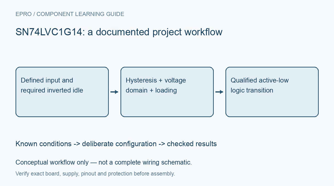
SN74LVC1G14 Inverter: 7 Checks for Active-Low Schmitt Signal Paths
SN74LVC1G14 checks for inverted idle states, Schmitt thresholds, down-translation, output contention and powered-off behavior. This is a documentation-based planning guide, not a report of independent hands-on testing.
1. Translate the inversion into the application state
The SN74LVC1G14 is one Schmitt-trigger inverter, not the noninverting function of a 1G17 buffer. A high input produces a low output and a low input produces a high output. Trace that inversion through the receiving enable, reset or interrupt before choosing pull-up and pull-down states. A clean edge with the wrong idle polarity can activate a downstream function during startup. Confirm the package pinout and logic truth table rather than relying on a shortened part label or extracted text that loses an inversion bar. Manufacturer documentation.
2. Match voltage domains without assuming bidirectionality
The recommended supply range is 1.65 V to 5.5 V, with input voltages supported up to 5.5 V under the specified conditions. A 5 V signal can therefore be down-translated with an appropriate lower supply, but the output remains tied to the inverter’s own supply domain. It does not produce a 5 V high when powered at 3.3 V and is not a bidirectional open-drain translator. Check receiver thresholds and input ratings separately from the nominal voltage printed on a module. Manufacturer documentation.
3. Use both hysteresis boundaries in timing analysis
The positive-going and negative-going thresholds differ and depend on supply and specified limits. Hysteresis can clean a slow or noisy crossing, but is not a precision reference at half the rail. In an RC-conditioned input, resistor and capacitor tolerance, leakage and the two threshold bands all influence delay. Analyze assertion and release separately because the inverter reverses their output meaning. A typical switching threshold cannot establish a guaranteed reset pulse width or a precise analog alarm point across all operating conditions. Manufacturer documentation.
4. Do not mistake edge cleanup for one-event detection
A mechanical contact or noisy cable can repeatedly cross both Schmitt boundaries and generate several clean inverted pulses. The gate alone therefore does not guarantee one event per press or reject every transient. Define the minimum valid event and the acceptable response delay before adding filtering or software qualification. Test the downstream receiver’s event count using representative disturbances. A visually sharp low pulse can still be an unwanted application event, so signal shape and event validity need separate acceptance criteria. Manufacturer documentation.
Newest in the store


5. Keep the push-pull output away from contention
The output actively drives both high and low. Do not wire it directly together with another push-pull output or treat it as an open-drain reset source. Any shared-line arrangement needs a suitable reviewed interface. The drive-current headline is conditional, and the manufacturer warns that output capability can exceed what the device can sustain safely. Check load, current, package dissipation and ringing. A logic inverter must not become a power switch merely because it can generate fast edges into a light load. Manufacturer documentation.
6. Review partial-power-down and input termination
Ioff supports the specified partial-power-down behavior, but does not remove leakage or back-power paths through other components on the board. Include host, sensor, pull-up and protection networks in the sequencing review. There is no ordinary output-enable input to force an arbitrary disabled state while powered. Define the input whenever its source can disconnect, and provide local supply decoupling and appropriate routing. Slow-input tolerance also does not mean floating or continuously mid-rail inputs have no current-consumption consequences. Manufacturer documentation.
7. Qualify active-low behavior at the final receiver
Record supply, input states, threshold assumptions, output load, idle polarity, pulse count and timing. Exercise the intended action, cable removal, reset and power-up sequence using benign low-voltage signals. Check both logic levels at the receiving pin and verify no unintended active-low command appears before the source is configured. The resulting record should establish correct inversion and bounded conditioning while keeping contact qualification, surge protection, shared-line compatibility and application safety as separate requirements that a single Schmitt inverter cannot guarantee. Manufacturer documentation.
Related reading: SN74LVC1G17 Buffer: 7 Checks for Noninverting Schmitt Conditioning.
Catalog note: The exact-part search did not return a matching Epro listing during preparation. Check the current catalog; this guide makes no price, availability or included-accessory claim.